Surface roughening apparatus for metal stock and surface roughening method for metal stock

Active Publication Date: 2017-01-19
TOYOTA JIDOSHA KK
View PDF4 Cites 0 Cited by
  • Summary
  • Abstract
  • Description
  • Claims
  • Application Information

AI Technical Summary

Benefits of technology

The patent describes a surface roughening apparatus and method that can improve the bonding strength of metal stock. By using two molds with different protrusions, the metal stock can be pressed twice to create an undercut shape, resulting in a more uniform and reliable bond. This process is efficient and can be completed in a short period of time. Overall, the patent provides a solution for increasing the strength of metal stock through surface roughening.

Problems solved by technology

However, in the method using a laser, an increase in processing time and an increase in equipment cost cause an increase in manufacturing cost.
In the method using etching and the method using shot blasting, convex and concave portions formed on the surface of the metallic material have a small depth, which may make it difficult to obtain a sufficient bonding strength.
In such a structure, each ridge is plastically deformed by the roller at only one location, which results in an increase in the processing time for forming undercuts in all the grooves.

Method used


Image

  • Surface roughening apparatus for metal stock and surface roughening method for metal stock
  • Surface roughening apparatus for metal stock and surface roughening method for metal stock
  • Surface roughening apparatus for metal stock and surface roughening method for metal stock

Examples


first exemplary embodiment

[0039]Exemplary embodiments will be described below with reference to the drawings. The same elements are denoted by the same reference numerals throughout the drawings, and repeated descriptions thereof are omitted as appropriate.

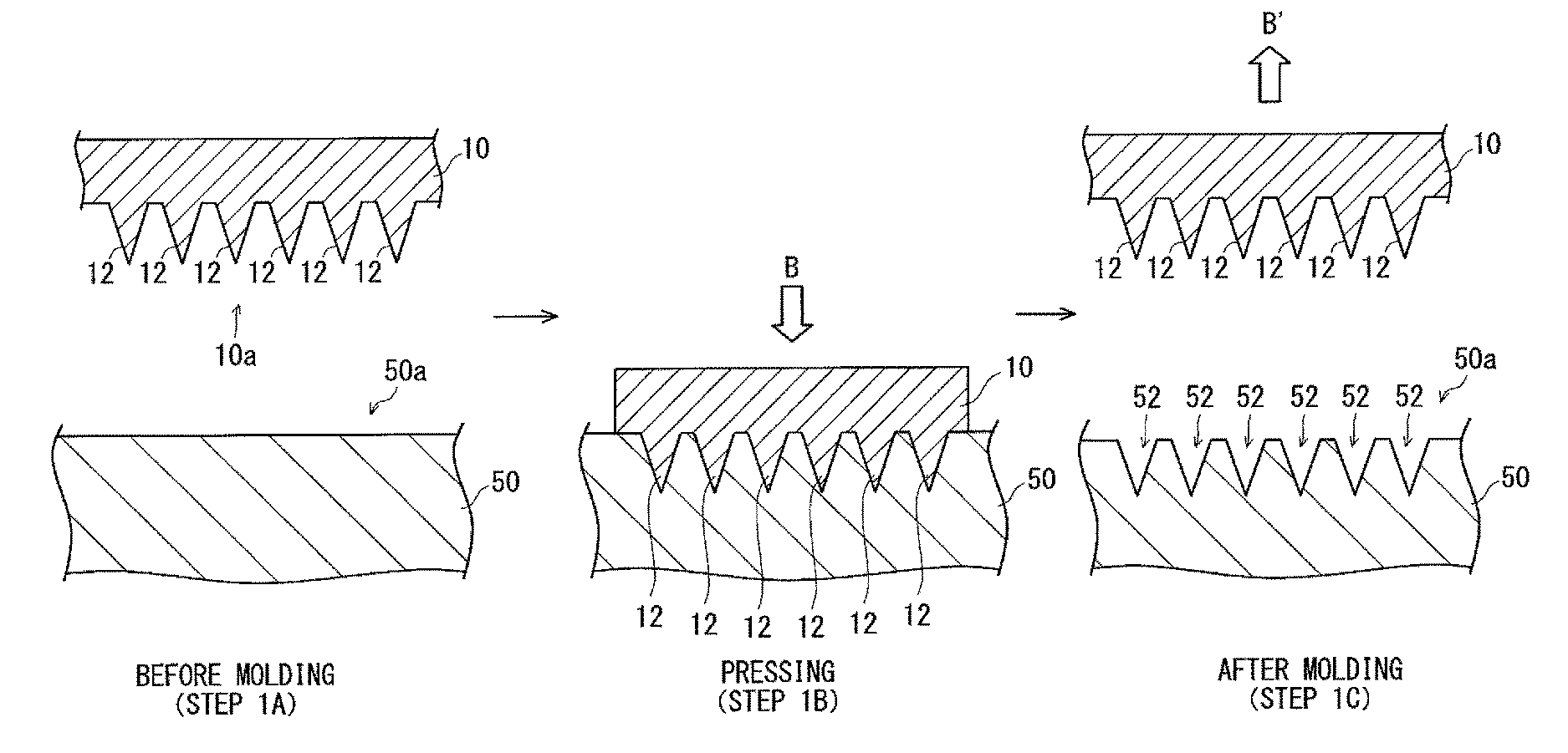
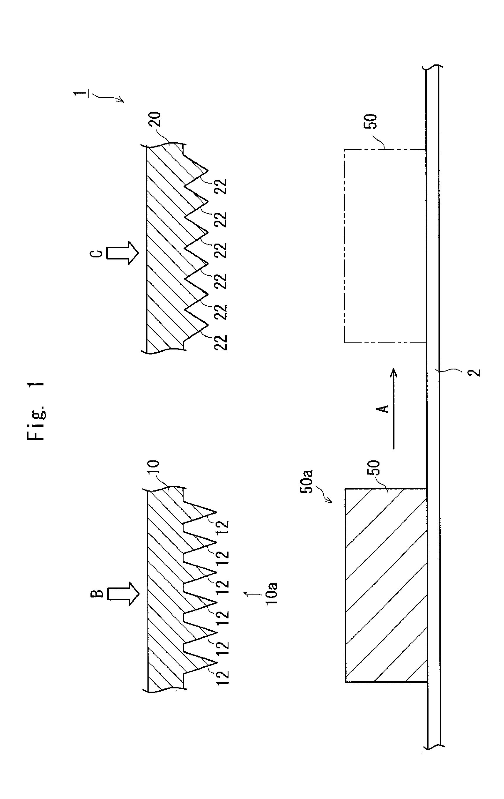
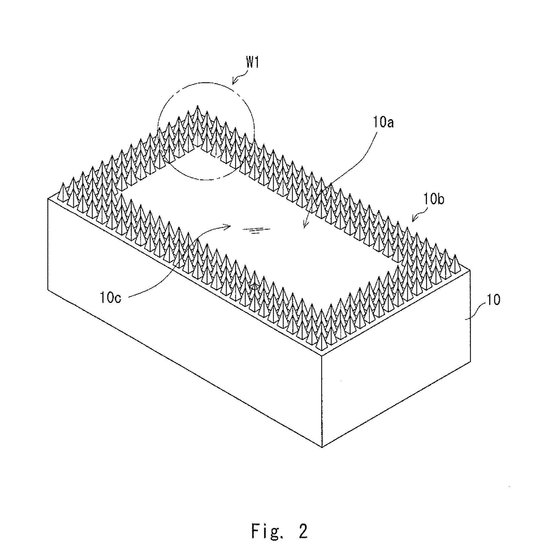
[0040]FIG. 1 is a diagram showing a surface roughening apparatus 1 according to a first exemplary embodiment. The surface roughening apparatus 1 includes a transport member 2, which transports a metallic material 50 (metal stock), a first mold 10 (first mold), and a second mold 20 (second mold). The transport member 2 transports the metallic material 50 to a location facing the first mold 10. As a result, an opposed surface 10a of the first mold 10 faces a surface 50a (first surface) of the metallic material 50. As indicated by an arrow A, the transport member 2 transports the metallic material 50 to a location facing the second mold 20. As a result, an opposed surface 20a of the second mold 20 faces the surface 50a of the metallic material 50.

[0041]The fi...

second exemplary embodiment

[0069]Next, a second exemplary embodiment will be described. In the second exemplary embodiment, the surface roughening method according to the first exemplary embodiment described above is applied to the formation of a pin-shaped fin (hereinafter referred to as a “pin fin”) which is formed in a cooler used for cooling electronic components and the like. Specifically, in the second exemplary embodiment, surface roughening of a metallic material is performed during the formation of a cooler made of a metallic material.

[0070]FIG. 11 is a diagram showing a method for producing an electronic device 70 according to the second exemplary embodiment. The electronic device 70 includes a plurality of electronic component structures 72. The electronic device 70 has a structure in which the plurality of electronic component structures 72 are joined together in a stacked state. Each electronic component structure 72 includes an electronic component 74, such as a power card, and a cooler 150. Eac...

modified example

[0096]Note that the disclosure is not limited to the exemplary embodiments described above, which can be modified as described below. For example, in the second exemplary embodiment described above, the formation the pin fins 164 and trimming are carried out in the same step as the roughening step. However, the formation of the pin fins 164 and trimming may be carried out in a step different from the roughening step.

[0097]FIG. 19 is a process chart showing an example in which the formation of the pin fins 164 and trimming are carried out in a step different from the roughening step. First, in step S102, the plurality of pin fins 164 are formed in the location corresponding to the pin-fin forming area 162 of the metallic material 50. This step S102 can be performed using the first molding portion 110 shown in FIG. 14 from which the roughening molding portion 10b (protrusions 12) is omitted. Next, in step S104, the outer peripheral portion 170 of the metallic material 50 is cut (trimm...


PUM

PropertyMeasurementUnit
Angleaaaaaaaaaa
Shapeaaaaaaaaaa
Heightaaaaaaaaaa

Abstract

A surface roughening apparatus includes a first mold and a second mold. The first mold has a plurality of first protrusions. The first mold presses a metallic material to form recesses corresponding to respective shapes of the first protrusions in a surface of the metallic material. The second mold has a plurality of second protrusions. After the first mold presses the metallic material, the second mold presses the metallic material, thereby deforming each recess into an undercut shape. A height of each first protrusion is greater than a height of each second protrusion. A tip angle of each first protrusion is smaller than a tip angle of each second protrusion.

Description

INCORPORATION BY REFERENCE[0001]This application is based upon and claims the benefit of priority from Japanese patent application No. 2015-139445, filed on Jul. 13, 2015, the disclosure of which is incorporated herein in its entirety by reference.BACKGROUND[0002]1. Technical Field[0003]The present disclosure relates to a surface roughening apparatus for a metal stock and a surface roughening method for a metal stock, and more particularly, to a surface roughening apparatus and a surface roughening method for roughening a surface of a metal stock.[0004]2. Description of Related Art[0005]It is known that in the case of bonding a metallic material and a resin to each other, the surface of the metallic material is roughened to increase the surface area, which leads to an improvement in bonding strength. Examples of the roughening method include methods using a laser, etching, and shot blasting. However, in the method using a laser, an increase in processing time and an increase in equi...

Claims


Application Information

Patent Timeline
IPC IPC(8): B21D22/02
CPCB21D22/02B21D37/10B21D53/022B23P9/00F28F3/022F28F3/12F28F21/065H01L23/3677F28D2021/0028F28F2255/14B21K23/00B21D17/02B21J13/02
Inventor TOMIOKA, AKINORIINOSHITA, HIROFUMI
Owner TOYOTA JIDOSHA KK
Why Eureka
Try Eureka