
Cable Spools with Sheaves

a cable spool and sheath technology, applied in the field of reel systems, can solve the problems of affecting the performance of pneumatic control signals, affecting the operation of the reel assembly, and affecting the operation of the mechanical control system of the pneumatically driven mechanical control system used to control the reel assembly operation

Active Publication Date: 2017-01-19
PATCO MACHINE & FABTING
View PDF8 Cites 17 Cited by
  • Summary
  • Abstract
  • Description
  • Claims
  • Application Information

AI Technical Summary

Benefits of technology

The patent describes a reel assembly for holding and deploying cable, hose, and umbilical connections. The assembly includes a spool assembly with a frame and a drum, an air motor, a sheave, and an electro-pneumatic drive unit. The assembly also includes a local electronic control unit (ECU) and one or more sensors to detect force, length of deployment, or both. The assembly can be controlled by a remote electronic control unit (RECU) or a combination of both the local and remote ECUs. The technical effects of the invention include improved handling and control of cable, hose, and umbilical connections, as well as increased efficiency and safety during deployment.

Problems solved by technology

Currently, the pneumatically driven mechanical control systems used to control the reel assembly operation suffer from various shortcomings.
For example, there are limitations on the locations of reel assemblies and a remote control stand because pneumatic control signals are subject to decreasing performance such as slower responses as the distance between the reel and the remote control stand increases.
In addition, current reel assemblies do not provide much feedback to the operator about the actual conditions of the cable / hose, such as accurate information about the actual tension on the cable / hose or how much of the cable / hose has been deployed.

Method used


Image

  • Cable Spools with Sheaves
  • Cable Spools with Sheaves
  • Cable Spools with Sheaves

Examples


Embodiment Construction

[0028]The elements illustrated in the figures interoperate as explained in more detail below. Before setting forth the detailed explanation, however, it is noted that all of the discussion below, regardless of the particular implementation being described, is exemplary in nature, rather than limiting.

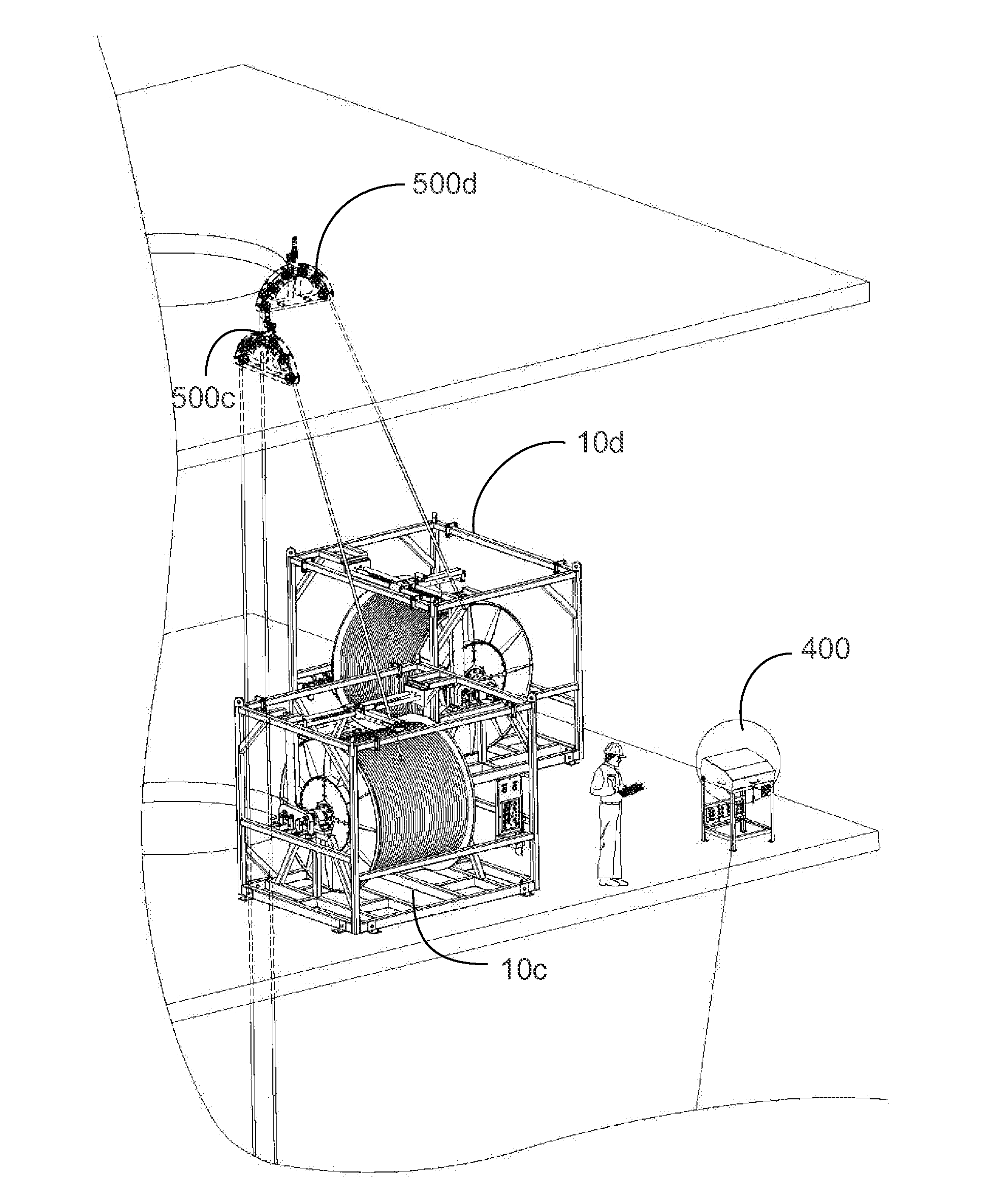
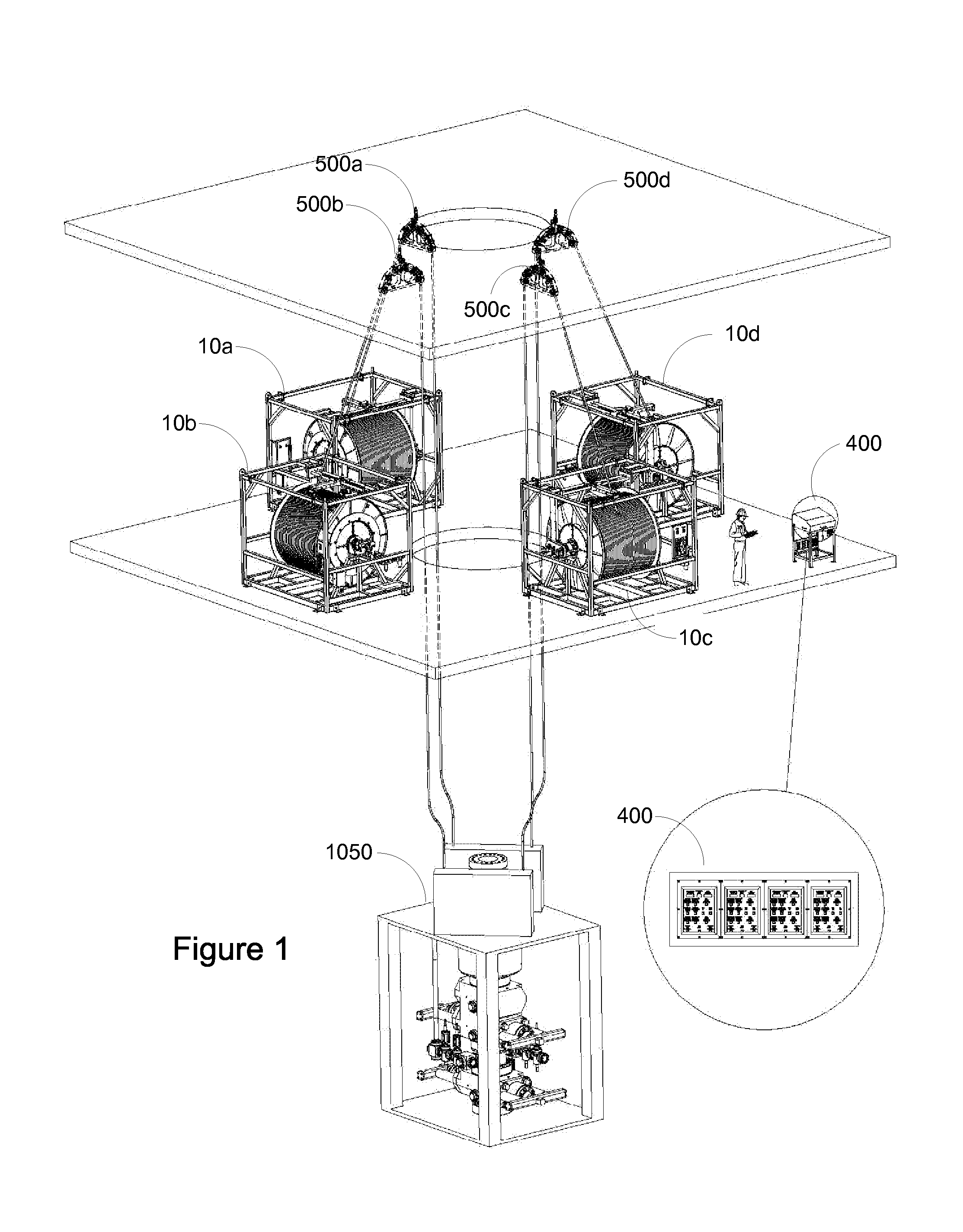
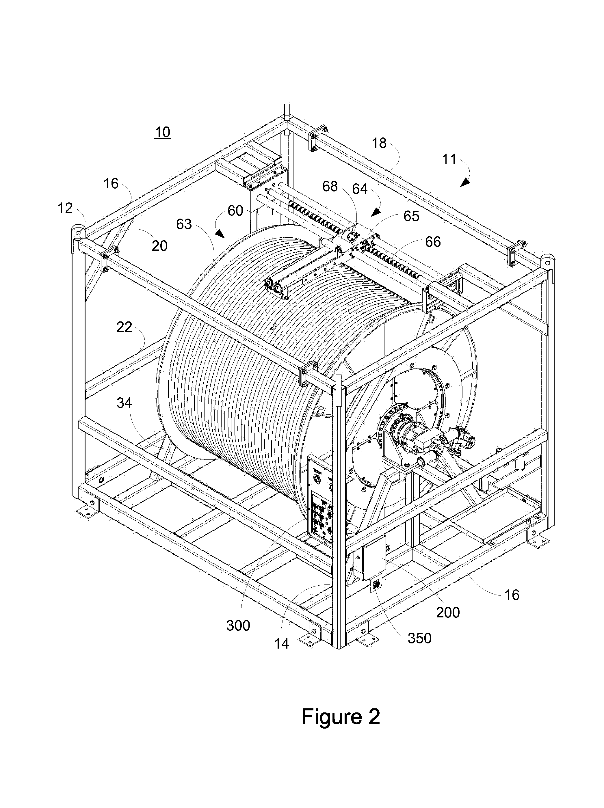
[0029]Referring to FIG. 1, an exemplary configuration of cable / hose reel assemblies 10a-d is shown. Although the terms “cable,”“hose,”“umbilical,” and “cable / hose” are used to describe various aspects of the embodiments described herein, it should be understood by one of ordinary skill in the art that the embodiments may be used in combination with cables, hoses, umbilical connections and the like and that use of the terms is exemplary in nature and not limiting. As illustrated, the configuration includes four reel assemblies 10a-d operating in conjunction with associated turn-down sheaves 500a-d to provide various cables, hoses and the like to a BOP stack. Each reel assembly 10a-d may ...


PUM


Abstract

A spooling system for deploying cable, hose, and / or umbilical connections may include a drum, an air motor, a sheave having one or more sensor, and an electronic control unit coupled to an electro-pneumatic drive for controlling the system. The sensors may provide information to the electronic control unit, such as a measured line tension and / or a length of cable, hose or umbilical connection that has been deployed, and the information may be displayed on the electronic control unit. The electronic control unit also may allow an operator to rotate the reel, stop rotation of the reel, increase or decrease the speed of rotation of the reel, increase or decrease pressure and / or line tension, and / or select between a normal mode of operation and a tensioning mode of operation.

Description

[0001]This application is a continuation of and claims benefit of priority from U.S. patent application Ser. No. 14 / 802,814 filed Jul. 17, 2015, which is incorporated by reference in its entirety.BACKGROUND OF THE INVENTION[0002]1. Technical Field[0003]The present application relates to reel systems for the receiving, storage, and deploying of cables (such as one or more electrical lines), hoses, umbilical connections (such as bundles of hydraulic lines, electrical lines, cables, hoses, and / or combinations thereof) and the like.[0004]2. Related Art[0005]Subsea blowout prevention equipment (BOP) uses large, specialized valves or similar mechanical devices, usually installed redundantly in stacks, to seal, control and monitor oil and gas wells. Redundant sub-sea control pods are used to control the valves of the BOP stack, some of which are referred to in the industry as blue and yellow pods. The pods of the BOP stack are controlled by cables, hoses, umbilical connections and the like...

Claims


Application Information

Patent Timeline
Patent Type & Authority Applications(United States)
IPC IPC(8): E21B19/22B65H75/44G05B15/02
CPCE21B19/22G05B15/02B65H2701/34B65H2701/33B65H75/4489B65H75/38B65H2551/10B65H2557/11E21B33/064
Inventor DION, DENNIS
Owner PATCO MACHINE & FABTING
Learn More