Cooling system for a vehicle

a technology for cooling systems and vehicles, applied in the direction of combustion-air/fuel-air treatment, machines/engines, fuel air intakes, etc., can solve the problems of limiting the the relative complexity of the cooling system, and achieve the effect of simple construction of the cooling system and high degree of efficiency of the cooling system

Active Publication Date: 2017-01-19
DR ING H C F PORSCHE AG
View PDF16 Cites 0 Cited by
  • Summary
  • Abstract
  • Description
  • Claims
  • Application Information

AI Technical Summary

Benefits of technology

[0015]The low temperature cooling circuit may comprise at least one low temperature cooler around which air flows and through which cooling water flows, the charge air cooler that can be cooled via the cooling water of the low temperature cooling circuit, and a low temperature cooling water pump. The high temperature cooling circuit may comprises at least one high temperature cooler around which air flows and through which cooling water flows, the drive assembly that can be cooled via the cooling water of the high temperature cooling circuit, the exhaust gas turbocharger that can be cooled via the cooling water of the high temperature cooling circuit, a high temperature cooling water pump and an exhaust gas turbocharger after run pump. A first end of the coupling line may engage the charge air cooler of the low temperature cooling circuit of the cooling system and a second end thereof may engage the high temperature cooling circuit of the cooling system downstream of the exhaust gas turbocharger after run pump. This connection of the coupling line is particularly advantageous for ensuring a simple construction of the cooling system and for ensuring a high degree of efficiency of the cooling system.

Problems solved by technology

However, the separate cooling water compensation tanks bring about a relatively complex construction of the cooling system.
If there is a common compensation tank is provided for both cooling circuits of the system disclosed in DE 10 2007 061 495 A1, there is the risk of the coolant flowing out of the high temperature cooling circuit into the low temperature cooling circuit, thereby limiting the efficiency of the cooling system is limited.

Method used


Image

  • Cooling system for a vehicle
  • Cooling system for a vehicle

Examples


Embodiment Construction

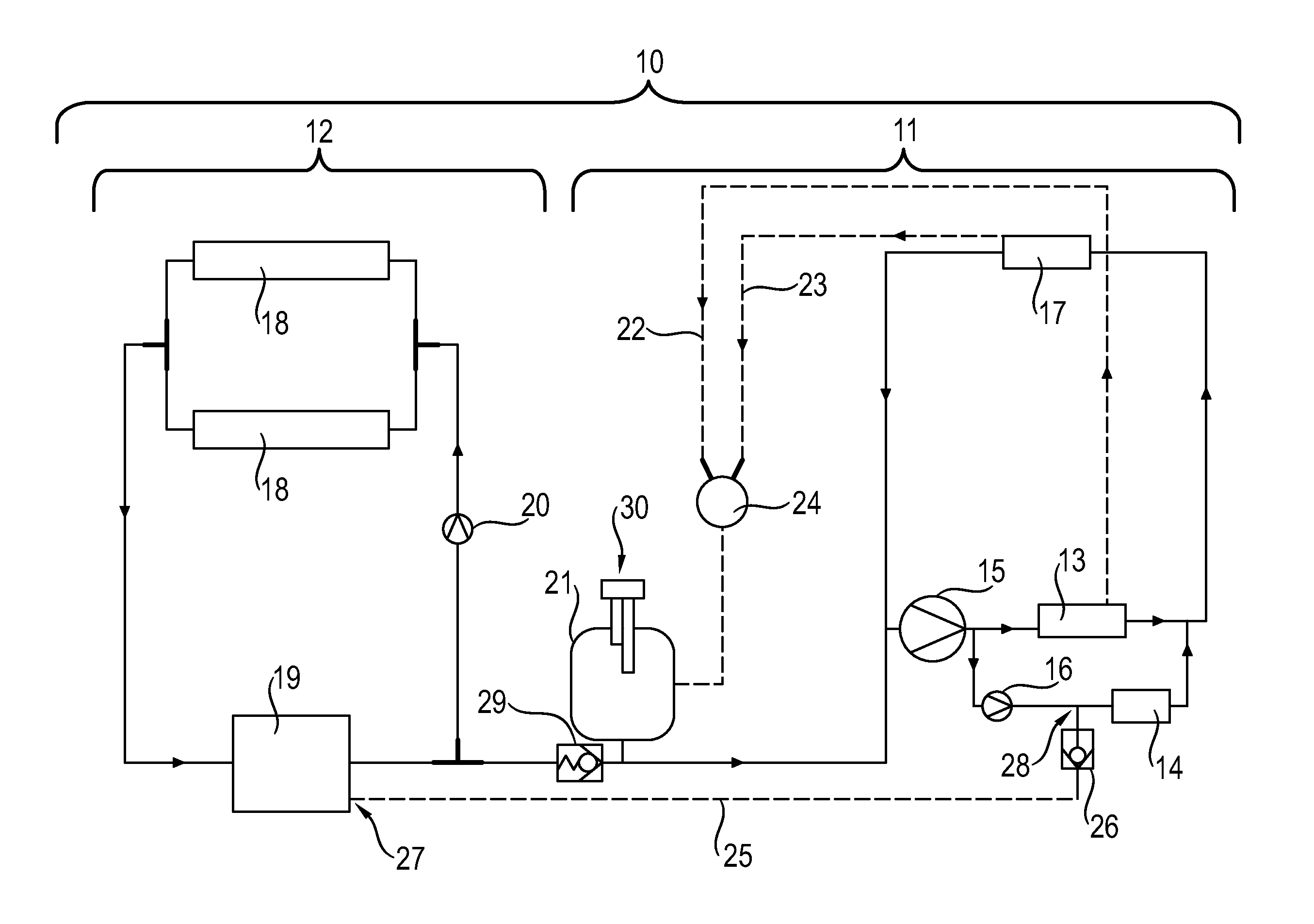
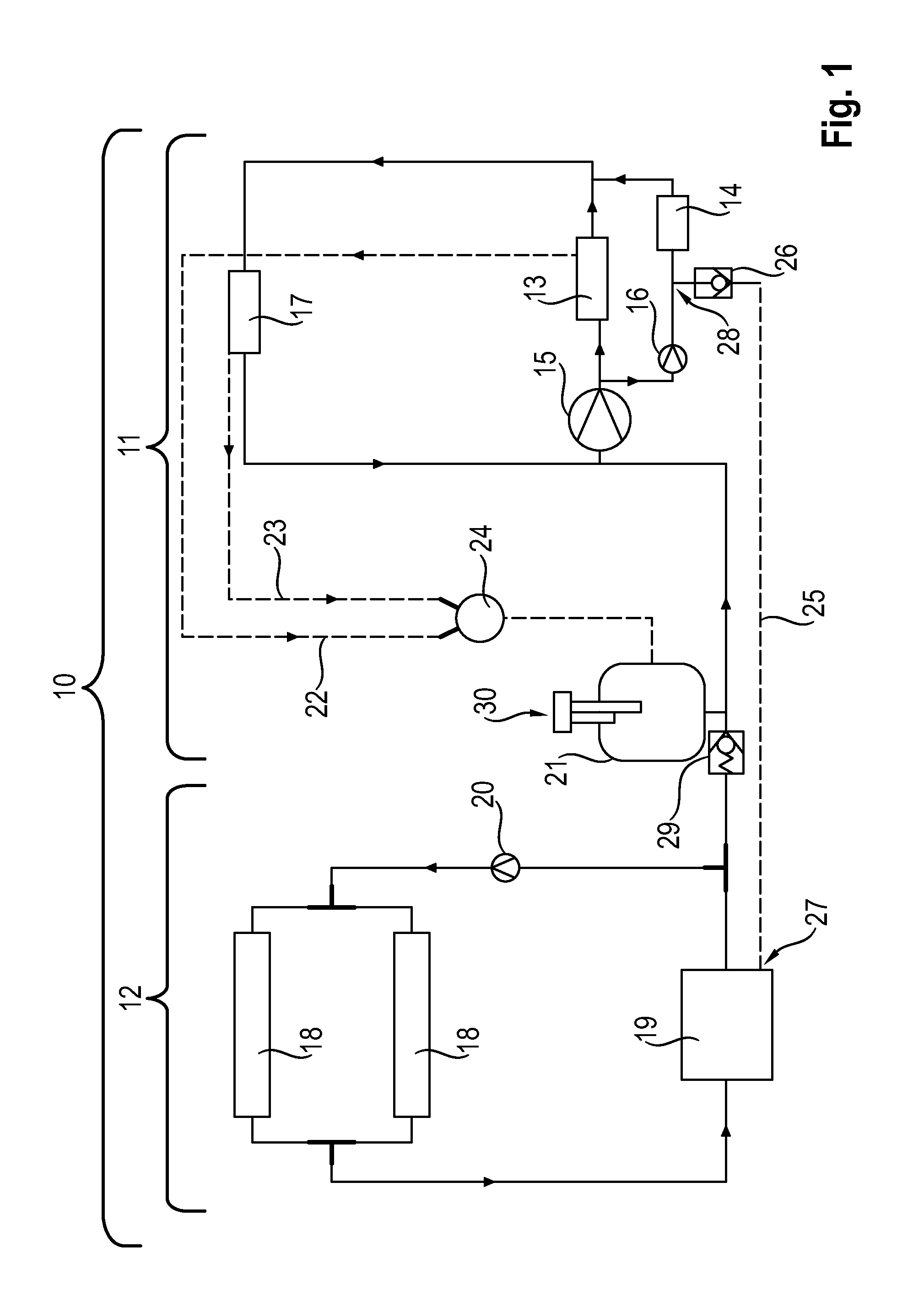
[0018]FIG. 1 is a block circuit diagram of a cooling system 10 for a vehicle according to the invention. The cooling system 10 comprises a high temperature cooling circuit 11 and a low temperature cooling circuit 12.

[0019]The high temperature cooling circuit 11 of the cooling system 10 cools a drive assembly 13 and an exhaust gas turbocharger 14. The high temperature cooling circuit 11 comprises a high temperature cooling circuit pump 15 to supply the assemblies that are to be cooled via the high temperature cooling circuit 11 with cooling water. The rotational speed of the pump 15 is dependent on the rotational speed of the drive assembly 13. The high temperature cooling circuit 11 also comprises an exhaust gas turbocharger after run pump 16, the rotational speed of which can be adjusted independently of the rotational speed of the drive assembly 13. Accordingly, cooling water required for cooling the drive assembly 13 and the exhaust gas turbocharger 14 can be circulated with the ...


PUM


Abstract

A cooling system (10) for a vehicle has a high temperature cooling circuit (11) for cooling a drive assembly (13) and an exhaust gas turbocharger (14) and has a low temperature cooling circuit (12) for cooling a charge air cooler (19). The high temperature cooling circuit (11) and the low temperature cooling circuit (12) are coupled via a coupling line (25), into which a nonreturn valve (26) is connected. The nonreturn valve (26) is opened or closed depending on the pressure ratio between the high temperature cooling circuit (11) and the low temperature cooling circuit (12). The high temperature cooling circuit (11) and the low temperature cooling circuit (12) can be vented via a common cooling water compensation tank (21) only in defined operating states when the nonreturn valve (26) of the coupling line (25) is open.

Description

CROSS REFERENCE TO RELATED APPLICATION[0001]This application claims priority under 35 USC 119 to German Patent Appl. No. 10 2015 111 407.0 filed on Jul. 14, 2015, the entire disclosure of which is incorporated herein by reference.BACKGROUND[0002]1. Field of the Invention[0003]The invention relates to a cooling system for a vehicle.[0004]2. Description of the Related Art[0005]Vehicles have cooling systems to cool components of the vehicle. It is known from practice that a cooling system for a vehicle with a drive assembly charged by exhaust gas, may comprise a high temperature cooling circuit and a low temperature cooling circuit. The high temperature cooling circuit cools the drive assembly and the exhaust gas turbocharger, whereas the low temperature cooling circuit cools a charge air cooler and therefore for the charge air.[0006]The high temperature cooling circuit and the low temperature cooling circuit are separated from each other and can be vented separately via separate cooli...

Claims


Application Information

Patent Timeline
Patent Type & Authority Applications(United States)
IPC IPC(8): F01P11/02F01P3/20F02M35/10F02B37/00F02B39/00
CPCF01P11/0285F02B37/00F02B39/005F01P2060/12F02M35/10157F01P3/20F02M35/10268F01P3/12F01P11/0204F02B29/0406F01P7/165F01P11/029Y02T10/12
Inventor ROEHM, HEIKOOSLISLOK, MIROSLAW
Owner DR ING H C F PORSCHE AG
Why Eureka
Try Eureka