Electromechanical brake booster

a brake master cylinder and electronic technology, applied in the direction of brake systems, vehicle components, transportation and packaging, etc., can solve the problems of high bernoulli force, slow brake pedal lever return using hydraulic pressure in the brake master cylinder, etc., to improve the return of the brake pedal lever

Active Publication Date: 2017-01-26
VOLKSWAGEN AG
View PDF3 Cites 2 Cited by
  • Summary
  • Abstract
  • Description
  • Claims
  • Application Information

AI Technical Summary

Benefits of technology

[0008]It is therefore an object of the present invention

Problems solved by technology

Due to friction and hysteresis effects, the return of the brake pedal lever using hydraulic pressure in the brake master cylinder may be slower than desired under certain circumstances.
From time to time, the

Method used


Image

  • Electromechanical brake booster
  • Electromechanical brake booster
  • Electromechanical brake booster

Examples


Embodiment Construction

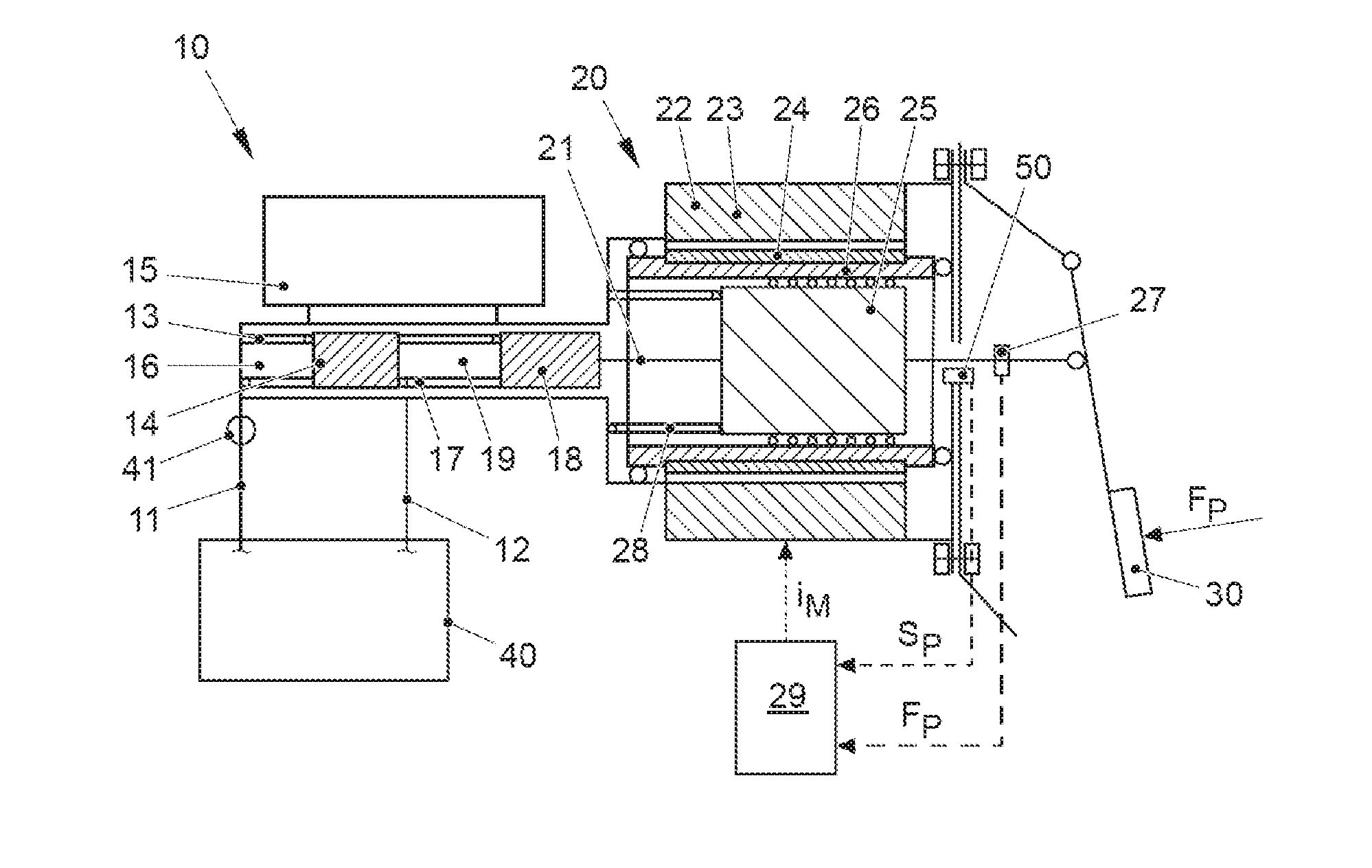
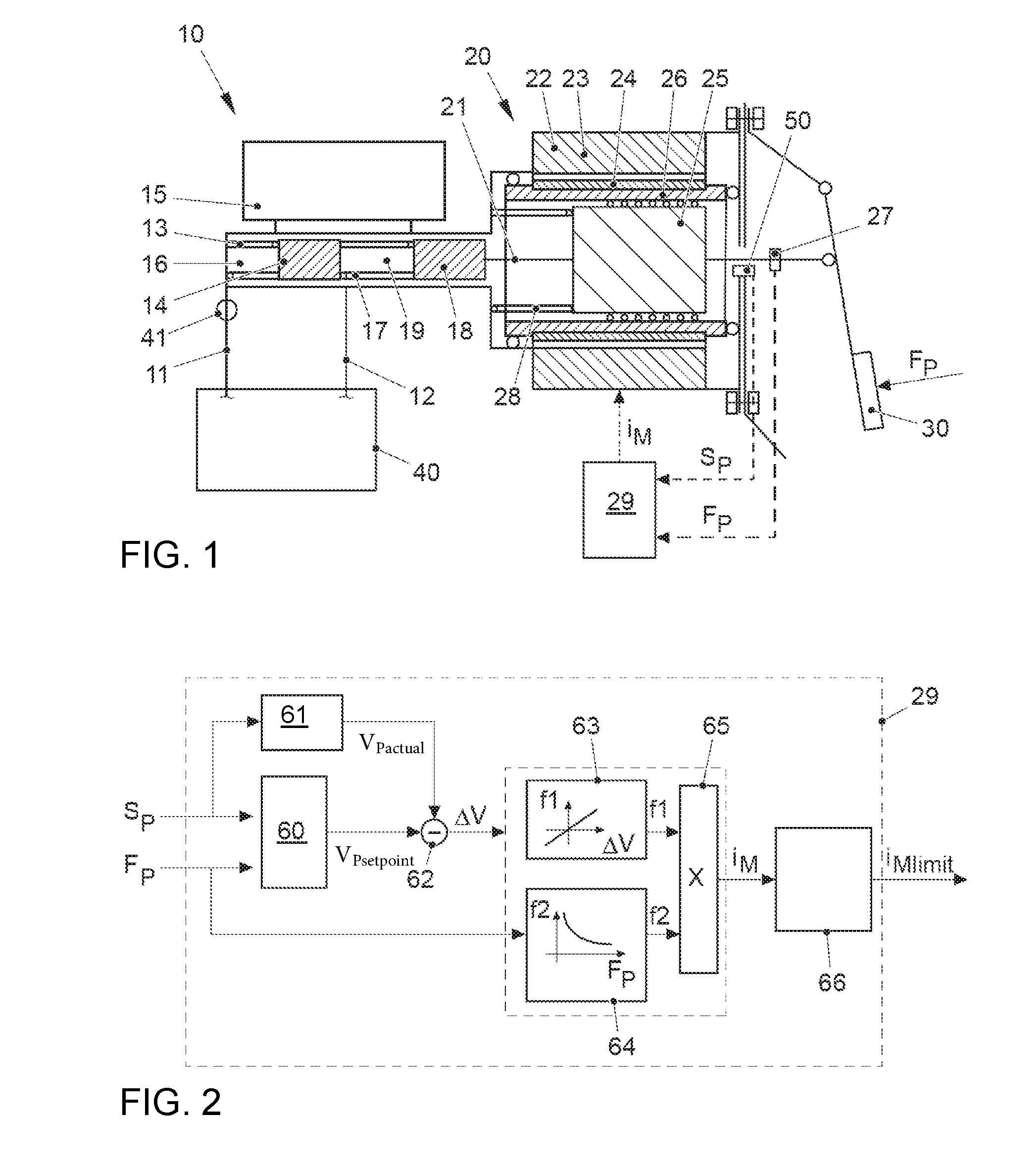
[0032]The exemplary embodiment in FIG. 1 shows a vehicle brake system comprising a brake master cylinder 10, an electromechanical brake booster 20 and a brake pedal lever 30. An ESP hydraulic unit 40, via which wheel brakes of the individual vehicle wheels are activated, is connected to tandem brake master cylinder 10.

[0033]Brake master cylinder 10 is connected to hydraulic unit 40 via two brake circuits 11 and 12. The two brake circuits 11 and 12 are activated via a first secondary piston 14 supported by a first return spring 13 and by a second primary piston 18 supported by a second spring 17. First spring 13 is used to push back secondary piston 14 so that brake fluid is able to flow back from a reservoir 15 into a first pressure chamber 16 of brake master cylinder 10. If a leak occurs in second hydraulic brake circuit 12, additional spring 17 is used to separate secondary piston 14 from primary piston 18, so that brake fluid is able to flow out of reservoir 15 into another press...


PUM


Abstract

An electromechanical brake booster having a plunger rod for connecting a brake pedal lever to a brake master cylinder, a gear motor, which is coupled with the plunger rod, and a control device for driving the gear motor. A pedal force variable representing the pedal force and a plunger rod motion variable representing the motion of the plunger rod are supplied to the control device as input variables. The control device is configured to determine a setpoint return velocity for the plunger rod with the aid of the plunger rod motion variable and an actual return velocity for the plunger rod and the pedal force variable from the setpoint return velocity and to generate an activation signal for the gear motor. This makes it possible to improve the brake release behavior and to reduce high Bernoulli forces at the end stop for the starting position of the brake pedal lever.

Description

[0001]This nonprovisional application claims priority under 35 U.S.C. §119(a) to German Patent Application No. 10 2015 213 707.4, which was filed in Germany on Jul. 21, 2015, and German Patent Application No. 10 2016 210 369.5, which was filed in Germany on Jun. 10, 2016, and both of which are herein incorporated by reference.BACKGROUND OF THE INVENTION[0002]Field of the Invention[0003]The invention relates to an electromechanical brake booster, comprising a plunger rod for coupling a brake pedal lever to a brake master cylinder, a gear motor, which is coupled with the plunger rod, and a control device, which is connected to the gear motor for the purpose of driving the same.[0004]Description of the Background Art[0005]An electromechanical brake booster is known, for example, from DE 10 2007 032 501 A1. Due to the connection between the brake pedal lever and the brake master cylinder, in contrast to systems using a pedal simulator, the pedal effort applied by the driver may be used ...

Claims


Application Information

Patent Timeline
IPC IPC(8): B60T13/74
CPCB60T13/745
Inventor DOBBERPHUL, TIMOSCHNEIDER, THOMASKESSELS, JOOSTNEEF, BARBARA
Owner VOLKSWAGEN AG
Why Eureka
Try Eureka