Low-construction trolley for wire rope hoist

Active Publication Date: 2017-01-26
KONECRANES GLOBAL
View PDF11 Cites 7 Cited by
  • Summary
  • Abstract
  • Description
  • Claims
  • Application Information

AI Technical Summary

Benefits of technology

The invention describes a solution for reducing twisting and balancing stresses during hoisting events, by establishing symmetrical positioning of support points for the hoisting rope in relation to the main support. This reduces the risk of twisting and load-related stresses on the hoisting member and the load. The solution also allows for increased diameter and shorter length of the rope drum, reducing drifting of the rope and twisting risks. Additionally, the placement of the hoisting motor under the beam or rail, on the opposite side of the rope drum, further reduces twisting risks and enables more options to secure the hoaling rope to the trolley frame. Furthermore, uniform bearing contact of the bearing wheels is achieved, reducing wear and ensuring smooth travel of the trolley without additional stress.

Problems solved by technology

This causes imbalance on the opposite sides of the main support, which is typically compensated for by a counterweight on the opposite side of the main support and opposite to the hoisting mechanism.
This asymmetry and long lever arms in relation to the main support cause, however, additional twisting of the rope system in relation to the vertical axis in a load hoisting and lowering situation, and consequently harmfully large bending moment and the resulting additional stress on the trolley, on the bearing wheels, for example, and thus additional stress also on the main support.
Disproportional load may cause premature wear and tear on the bearing wheels and / or the guiding surfaces on the beam or rail that the main support potentially has, creating jerking movement for the trolley.
In addition, if the fixing of the hoisting rope to the rope drum is typically located on the side of the trolley where the fixing point of the hoisting rope to the trolley frame is also located, the portion of the rope system that leads to a fixed fixing point may hit the portion of the rope system coming from the rope drum when the hoisting member is being lowered, which may wear and damage the hoisting rope.
In these, too, exactly the same problems are seen as in trolleys comprising a counterweight.

Method used


Image

  • Low-construction trolley for wire rope hoist
  • Low-construction trolley for wire rope hoist
  • Low-construction trolley for wire rope hoist

Examples


Embodiment Construction

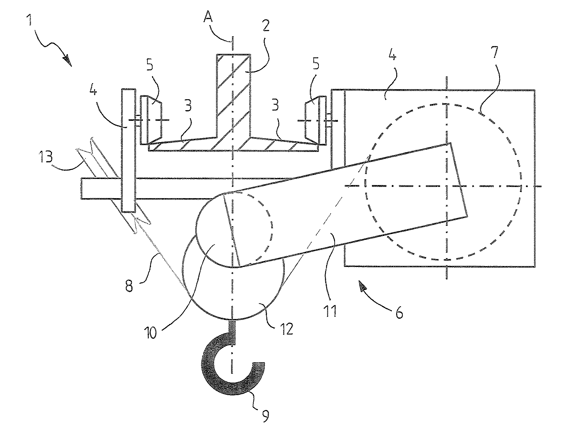
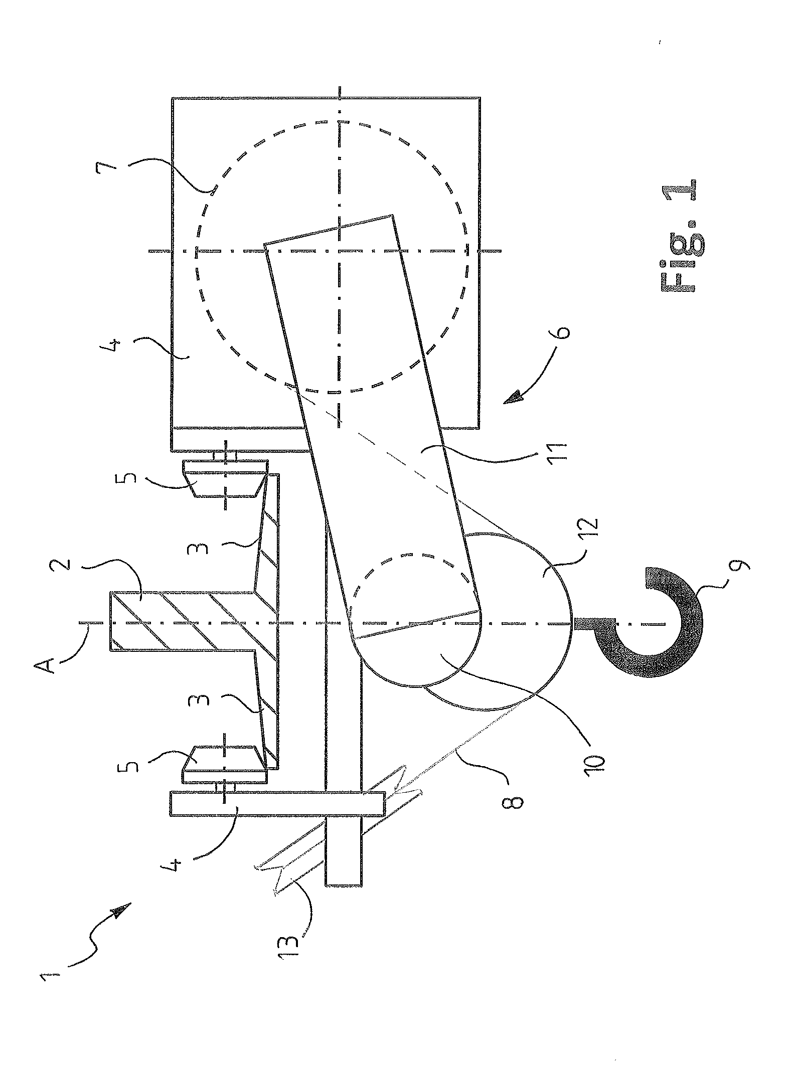
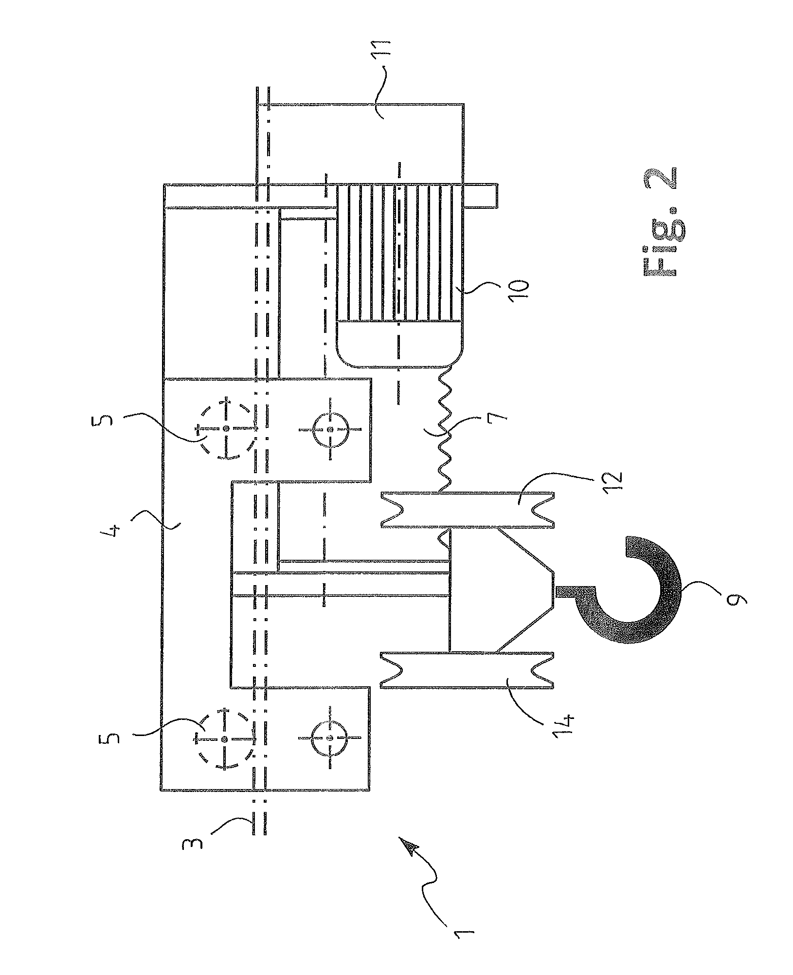
[0028]Referring to the Figures, at first to FIGS. 1-3, in particular, a low-construction trolley 1 for a wire rope hoist is seen, arranged to travel along the lower flange 3 of a horizontal beam or of a rail 2, like here. The rail 2 typically establishes the main support of a bridge crane, or is included in it as its lowest part.

[0029]The trolley 1 is shown as a simplified functional diagram, showing only what is needed to understand the invention.

[0030]The trolley 1 comprises a frame 4 of the trolley, bearing wheels 5, and a hoisting mechanism 6.

[0031]The bearing wheels 5 are attached to the frame 4 of the trolley, and arranged to travel on the upper surface of the lower flange 3 of the rail 2, on both of its longitudinal edges, and at least some of are driven wheels to move the trolley 1. The actuator (moving mechanism of the trolley) for driving the bearing wheels 5 is not shown.

[0032]The hoisting mechanism 6 comprises a rope drum 7 for a hoisting rope 8, a hoisting member in coo...


PUM


Abstract

A low-construction hoist for a wire rope hoist is arranged to move along a lower flange of a horizontal beam or rail. The trolley includes a trolley frame; bearing wheels, which are fixed to the trolley body and arranged to move on the upper surface of the lower flange of the rail, a hoisting mechanism including a rope drum for a hoisting rope, a hoisting member in cooperation with the hoisting rope for hoisting a load, and a hoisting motor for driving the rope drum; whereby the rope drum is supported to a first side of the trolley frame so that the axle of the rope drum is parallel to the rail, and the hoisting member is arranged to move under the rail; whereby the hoisting rope is led from the rope drum to a fixing point in the trolley frame through at least a rope pulley arrangement of the hoisting member, whereby the fixing point of the hoisting rope to the trolley frame is located in the longitudinal direction of the trolley outside the end of the rope drum, or outside the vertical plane which is transverse in relation to the rail or beam and passing through the end of the rope drum.

Description

BACKGROUND OF THE INVENTION[0001]A low-construction trolley for a wire rope hoist, arranged to travel along a lower flange of a horizontal beam or rail, whereby the trolley comprises a trolley frame; bearing wheels that are attached to the frame of the trolley and arranged to travel on the upper surface of the lower flange of the beam or rail, and at least some of which are driven wheels to move the trolley; a hoisting mechanism comprising a rope drum for a hoisting rope, a hoisting member in cooperation with the hoisting rope for hoisting a load, and a hoisting motor for driving the rope drum; whereby the rope drum is supported to a first side of the trolley frame so that the axle of the rope drum is parallel to the beam or rail, and the hoisting member is arranged to move under the beam or rail; whereby the hoisting rope is led from the rope drum to a fixing point in the trolley frame through at least a rope pulley arrangement of the hoisting member.[0002]A low-construction trolle...

Claims


Application Information

Patent Timeline
IPC IPC(8): B66C11/06B66D1/36B66D1/14B66D1/12
CPCB66C11/06B66D1/12B66C19/00B66D1/14B66D1/36B66C9/14B66C9/10B66C11/16
Inventor LINDBERG, TEPPOKOKKO, HENRI
Owner KONECRANES GLOBAL
Why Eureka
Try Eureka