Panel of organic electroluminescent display

Inactive Publication Date: 2005-03-24
RITDISPLAY
View PDF7 Cites 30 Cited by
  • Summary
  • Abstract
  • Description
  • Claims
  • Application Information

AI Technical Summary

Benefits of technology

[0012] As mentioned above, the organic electroluminescent display panel of the invention has an isolation layer or encapsulating layer, which is at least one layer structure, disposed on the protecting layer and/or the substrate. Comparing with the prior art, the invention can misalign the pin-hole defects of the multiple isolation layers, so as to compensate the defects of the layers. In addition, at least one layer structure can extend the penetration path of water and oxygen, which can prevent the invasion of water and oxygen into inside of the component. Furthermore, the isolation layer of the invention can comprise several layers with different young's modulus. The layer with a lower young's modulus is sandwiched between the layers with higher young's modulus for providing a buffer effect. Accordingly, the stress between the isolation layers can be decreased. Moreover, a plurality of protrusions can make the isolation layer with a wave-like shape. This structure of the isolation layer can have more contact area and stronger adhesive force with other portions such as the protecting layer and the protr

Problems solved by technology

However, the organic electroluminescent component (the organic functional material) is very sensitive to water and oxygen, and may generate dark spots after exposing in atmosphere.
However, the formed inorganic film is not continuous since the surface of the organic electroluminescent component is not planar.
However, since the organic layer 43 has a poor thermal resistance, the high temperature may crack the organic layer 43, which results in the malfunction of this waterproof lay

Method used


Image

  • Panel of organic electroluminescent display
  • Panel of organic electroluminescent display
  • Panel of organic electroluminescent display

Examples


Example

[0021] First Embodiment

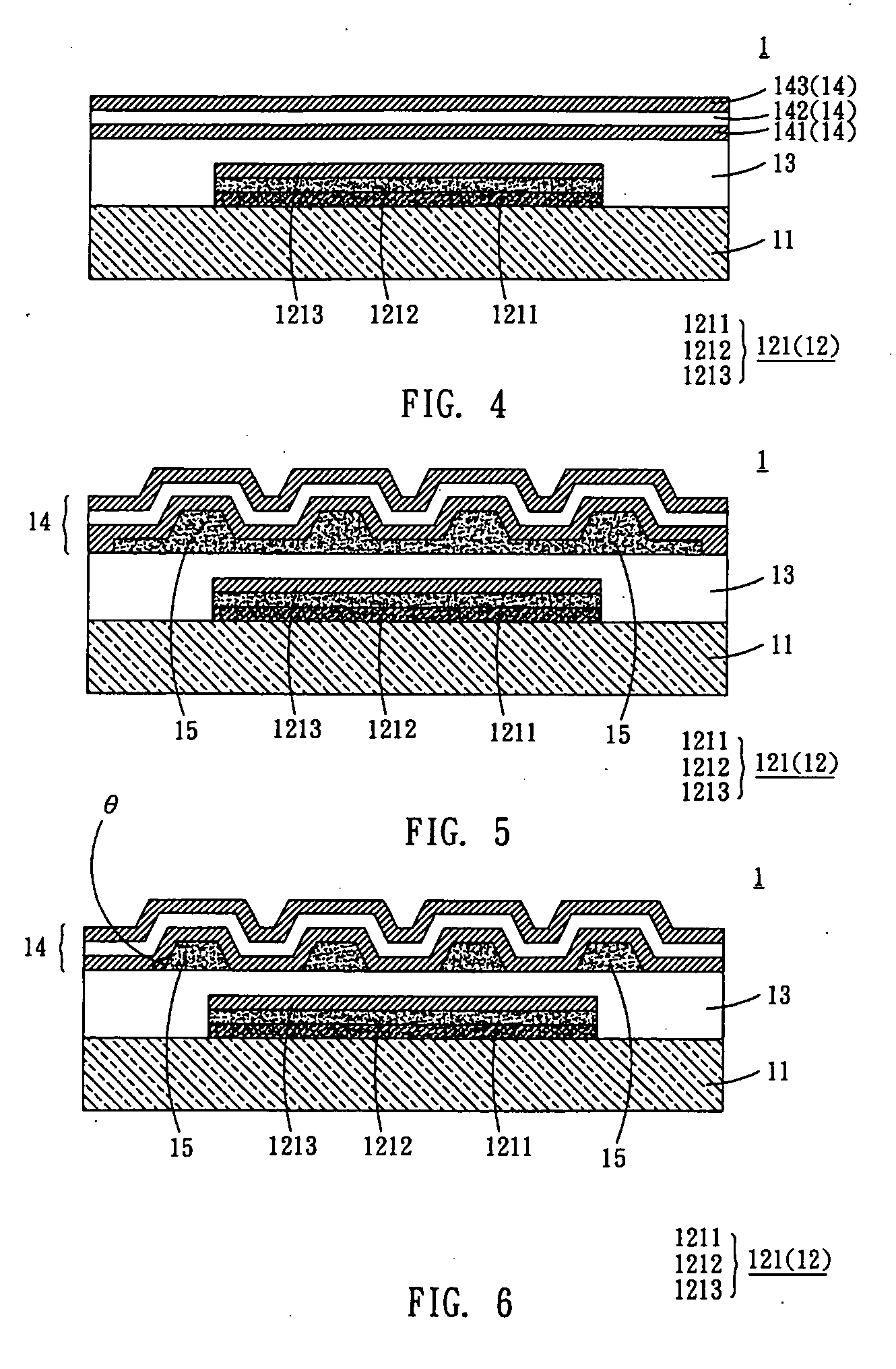
[0022] With reference to FIG. 4, an organic electroluminescent display panel 1 according to the first embodiment of the invention comprises a substrate 11, at least one organic light-emitting area 12, at least one protecting layer 13 and at least one isolation layer 14. In the embodiment, the organic light-emitting area 12 is disposed over the substrate 11 and comprises a plurality of pixels 121. The protecting layer 13 is disposed over the substrate 11 and the organic light-emitting area 12. The isolation layer 14 is disposed over the protecting layer 13.

[0023] In the present embodiment, the substrate 11 can be a flexible or a rigid substrate. The substrate 11 can also be a plastic or glass substrate. In particular, the flexible substrate or plastic substrate can be made of polycarbonate (PC), polyester (PET), cyclic olefin copolymer (COC), or metallocene-based cyclic olefin copolymer (mCOC). Of course, the substrate 11 can also be a silicon substrate.

[002...

Example

[0045] Second Embodiment

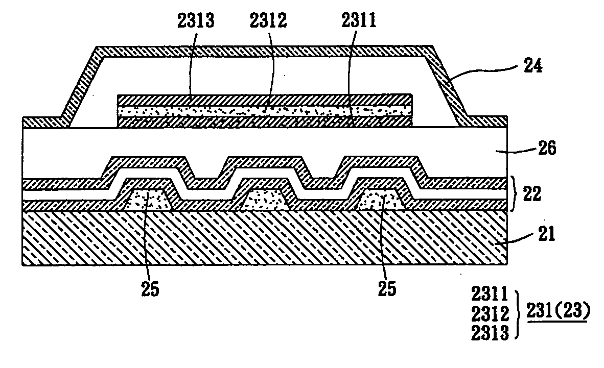
[0046] With reference to FIG. 12, an organic electroluminescent display panel 2 according to the second embodiment of the invention comprises a substrate 21, a plurality of isolation layers 22 and at least one organic light-emitting area 23. In the embodiment, the isolation layers 22 are disposed over the substrate 21 and comprise an inorganic material. The organic light-emitting area 23 is disposed over the isolation layers 22 and comprises at least one pixel 231.

[0047] The features and functions of the substrate 21, isolation layers 22, organic light-emitting area 23, pixels 231, first electrode 2311, organic functional layer 2312 and second electrode 2313 are the same to those described in the first embodiment, so the detailed descriptions are omitted here for concise purpose.

[0048] With reference to FIG. 12 again, the organic electroluminescent display panel 2 further comprises an encapsulating layer 24, which is disposed over the isolation layers 22. ...


PUM


Abstract

An organic electroluminescent display panel comprises a substrate, at least one organic light-emitting area, at least one protecting layer, at least one isolation layer and at least one protrusion. In this case, the organic light-emitting area comprises a plurality of pixels and is disposed over the substrate. The protecting layer is disposed over the substrate and the organic light-emitting area. The isolation layer is disposed over the protecting layer.

Description

BACKGROUND OF THE INVENTION [0001] 1. Field of Invention [0002] The invention relates to a display panel and, in particular, to an organic electroluminescent display panel. [0003] 2. Related Art [0004] The flat-panel displays have been developed with the trend towards high brightness, planar and thinner structures, and power saving. Accordingly, the organic electroluminescent (OEL) display panel is one of the most potential products in optoelectronics industries. The organic electroluminescent display panel uses the self-emitting property of organic functional materials to perform display purposes. The organic electroluminescent display comprises small molecule OLED (SM-OLED) and polymer light-emitting display (PLED) according to the molecular weight of the organic functional materials. [0005] However, the organic electroluminescent component (the organic functional material) is very sensitive to water and oxygen, and may generate dark spots after exposing in atmosphere. Accordingly...

Claims


Application Information

Patent Timeline
IPC IPC(8): H01L21/76H01L27/15H01L29/08H01L31/12H01L35/24H01L51/00H01L51/52
CPCH01L2251/5338H01L51/5237H10K2102/311H10K59/873H10K50/844
Inventor YANG, FU-HSIANGLEE, HSIN-CHENWU, ZHI-HAOCHANG, YIH
Owner RITDISPLAY
Why Eureka
Try Eureka