Aerobic Treatment System

a treatment system and aerobic technology, applied in the direction of sedimentation settling tanks, multi-stage water/sewage treatment, separation processes, etc., can solve the problems of increasing the operational cost of aerobic treatment systems, generating such electricity, and not being suitable for use in conventional septic systems

Active Publication Date: 2017-01-26
DECHRISTOFARO DAVID +3
View PDF4 Cites 1 Cited by
  • Summary
  • Abstract
  • Description
  • Claims
  • Application Information

AI Technical Summary

Problems solved by technology

In many instances, conventional septic systems may not be suitable for use in areas in which insufficient land is available to provide for proper leech fields, or in areas in which the soil conditions are inappropriate to provide the necessary retention times and drainage.
In some communities, the water table is too high to allow the leech field adequate treatment processing time before the wastewater encounters the resident groundwater.
The injection and circulation of air is driven by electricity, and the generation of such electricity typically adds to the operational costs of aerobic treatment systems, including additional maintenance expenses.
In addition, before wastewater leaving conventional aerobic holding treatment tanks can be properly returned to the environment, the wastewater may require a final clarifying treatment or disinfection.
In use, both filters and drainage fields require significant space and can become clogged with residual components of the wastewater exiting the aerobic holding treatment tank, thereby reducing efficiency.
Evapotranspiration beds are less commonly used in final clarifying treatment as they are expensive to maintain and require significant retention times to be effective.

Method used


Image

  • Aerobic Treatment System
  • Aerobic Treatment System

Examples


Embodiment Construction

[0023]For purposes of the description hereinafter, the terms “upper”, “lower”, “right”, “left”, “vertical”, “horizontal”, “top”, “bottom”, “lateral”, “longitudinal”, and derivatives thereof shall relate to the invention as it is oriented in the drawing figures. However, it is to be understood that the invention may assume various alternative variations, except where expressly specified to the contrary. It is also to be understood that the specific devices illustrated in the attached drawings, and described in the following specification, are simply exemplary embodiments of the invention. Hence, specific dimensions and other physical characteristics related to the embodiments disclosed herein are not to be considered as limiting.

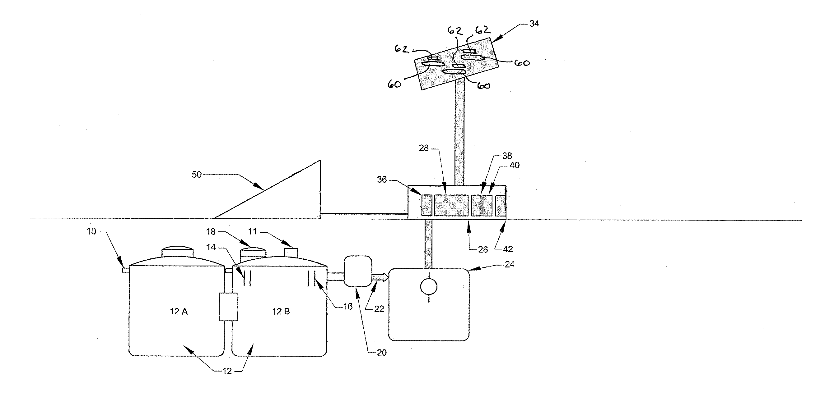
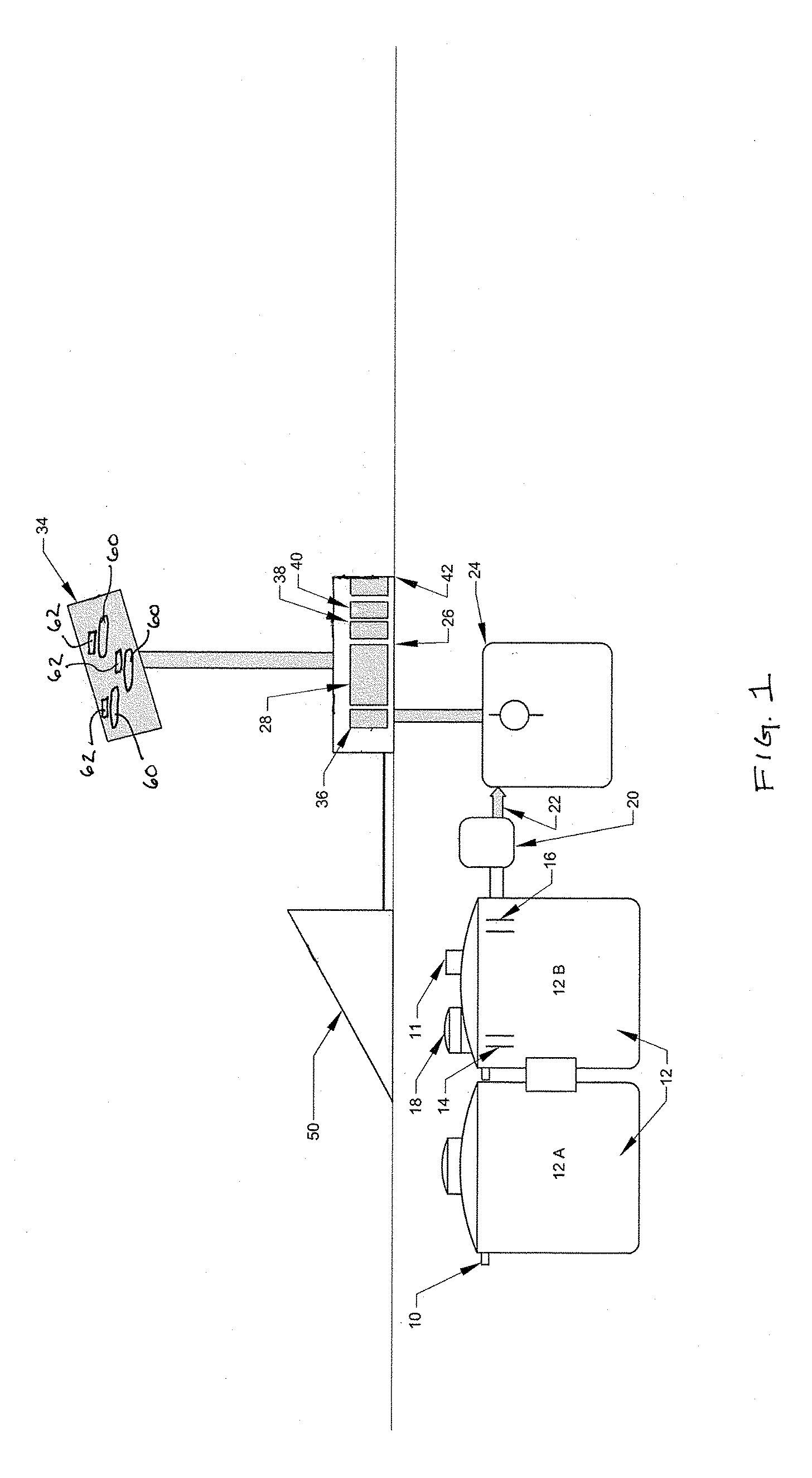
[0024]Referring to FIG. 1, wastewater from a commercial or residential source may enter an inlet 10 of an aerobic holding treatment tank 12. Aerobic holding treatment tank 12 may be disposed below ground-level and can have any appropriate volume sufficient to...


PUM

PropertyMeasurementUnit
diameteraaaaaaaaaa
diameteraaaaaaaaaa
volumeaaaaaaaaaa

Abstract

An aerobic treatment system is disclosed herein in which an aerobic holding treatment tank, having an inlet adapted to receive wastewater and an outlet adapted to discharge treated wastewater therefrom, is in communication with an aeration pump having an inlet nozzle in communication with the aerobic holding treatment tank for providing a source of air to the contents of the aerobic holding treatment tank. The aerobic treatment system may further include a generation pump disposed below ground level and in fluid communication with the aerobic holding treatment tank. The generation pump is provided in fluid communication with a high pressure pump in fluid access with an evaporator fan and misting nozzle. The system may further include electronics to connect to grid power, backup electronics for connection to auxiliary power sources, and at least one solar collector for providing a source of electricity.

Description

CROSS-REFERENCE TO RELATED APPLICATION[0001]The present application claims priority to U.S. Provisional Application Ser. No. 62 / 194,956, entitled “Solar Septic Treatment System”, and filed Jul. 21, 2015, the entire disclosure of which is hereby incorporated by reference.BACKGROUND OF THE INVENTION[0002]Field of the Invention[0003]The present invention is directed to aerobic treatment systems and, more particularly, is directed to a septic treatment system that utilizes evaporation to reduce and / or eliminate the need for soil absorption.[0004]Description of Related Art[0005]Septic systems and aerobic treatment systems have been conventionally used to treat wastewater in geographic areas in which a centralized sewage system is prohibitive or not cost-effective. In many instances, conventional septic systems may not be suitable for use in areas in which insufficient land is available to provide for proper leech fields, or in areas in which the soil conditions are inappropriate to provi...

Claims


Application Information

Patent Timeline
Patent Type & Authority Applications(United States)
IPC IPC(8): C02F9/00C02F1/32B01D1/00C02F1/04B01D21/02C02F1/00C02F1/12C02F3/02B01D1/20
CPCC02F9/00C02F3/02C02F1/325B01D1/0064C02F1/048B01D21/02C02F1/004C02F1/12B01D1/20Y02W10/37C02F1/32C02F2201/009C02F2203/002Y02A20/212Y02W10/10
Inventor JOSEPH, III, THOMAS A.BROEKER, MICHAELMEADOWS, BERRY L.DECHRISTOFARO, DAVID
Owner DECHRISTOFARO DAVID
Why Eureka
Try Eureka