Vacuum-actuated liquid disinfectant dispenser and system

a dispenser and liquid technology, applied in the direction of filtration separation, multi-stage water/sewage treatment, separation process, etc., can solve the problems of undigested solids, difficult and expensive acquisition of liquid chlorine in tablet form, and wastewater treatment leaving the unit requires additional treatmen

Active Publication Date: 2011-02-01
D I R MFG & SUPPLIES
View PDF5 Cites 1 Cited by
  • Summary
  • Abstract
  • Description
  • Claims
  • Application Information

AI Technical Summary

Benefits of technology

[0014]Because chlorine is added to the effluent contained by the system after a pumping cycle, a known volume of disinfectant can be added to the effluent wherein the volume of added disinfectant is a function of the effluent added to the holding chamber. Because the volume of accumulated disinfectant within the dosage container can be controlled with the pressure control device, the dosage container can consistently be filled with the same volume of disinfectant for each dosing. Therefore, the same volume of chlorine is dispensed into the aerobic treatment system after each pumping cycle. This results in more efficient use of available disinfectant than is disclosed in the prior art.

Problems solved by technology

Even after breakdown, however, the treated wastewater leaving the unit requires additional treatment or disinfection before being returned to the environment.
Because the bacteria cannot digest all of the solids, the undigested solids eventually settle out as sludge.
Until recently, the typical method of treating wastewater within an aerobic system was to cause the wastewater to come into contact with chlorine tablets, but chlorine in tablet form has traditionally been more difficult and expensive to acquire in solid form vis-à-vis chlorine in liquid form, such as common household bleach.

Method used


Image

  • Vacuum-actuated liquid disinfectant dispenser and system
  • Vacuum-actuated liquid disinfectant dispenser and system
  • Vacuum-actuated liquid disinfectant dispenser and system

Examples


Embodiment Construction

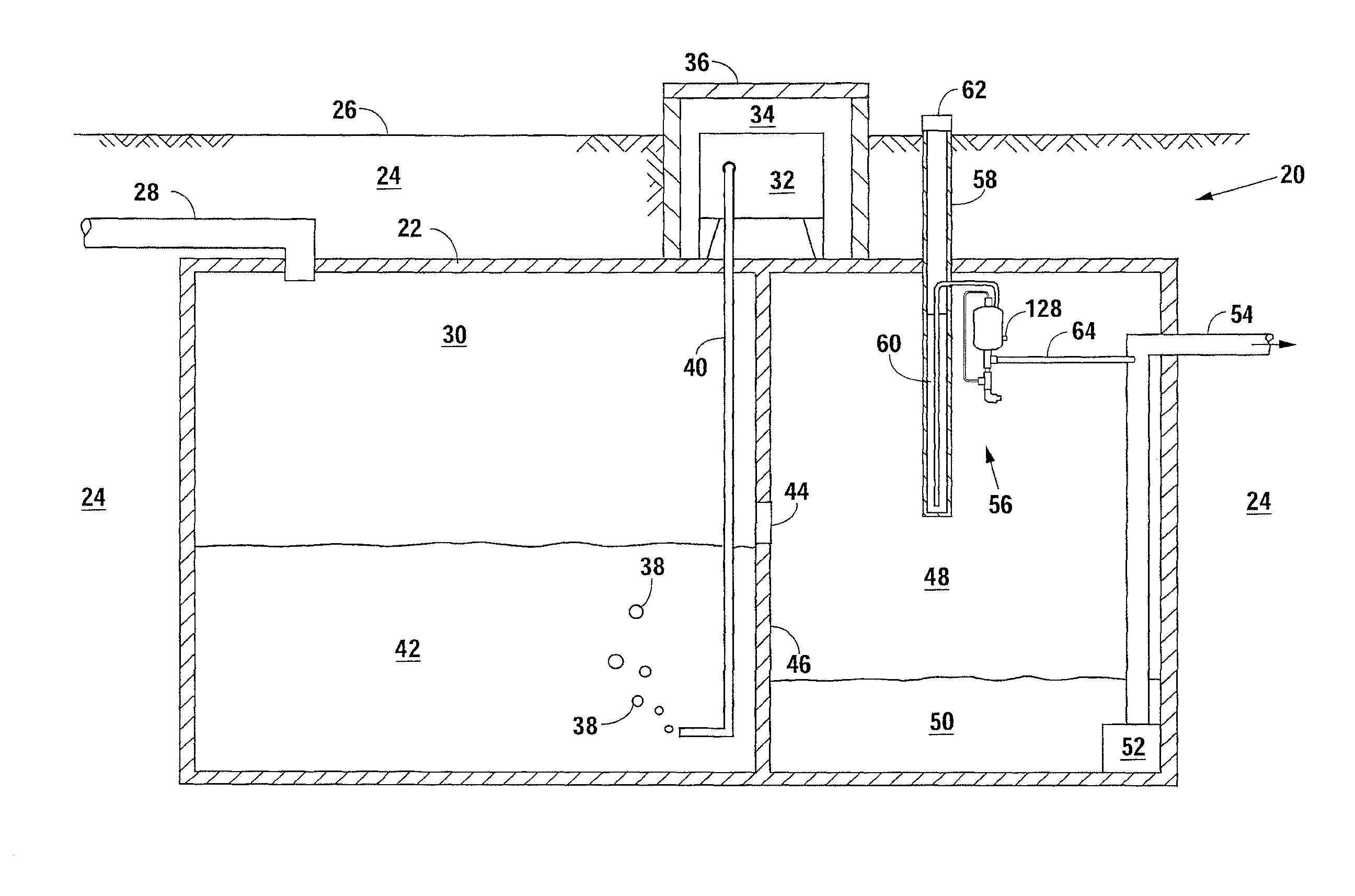
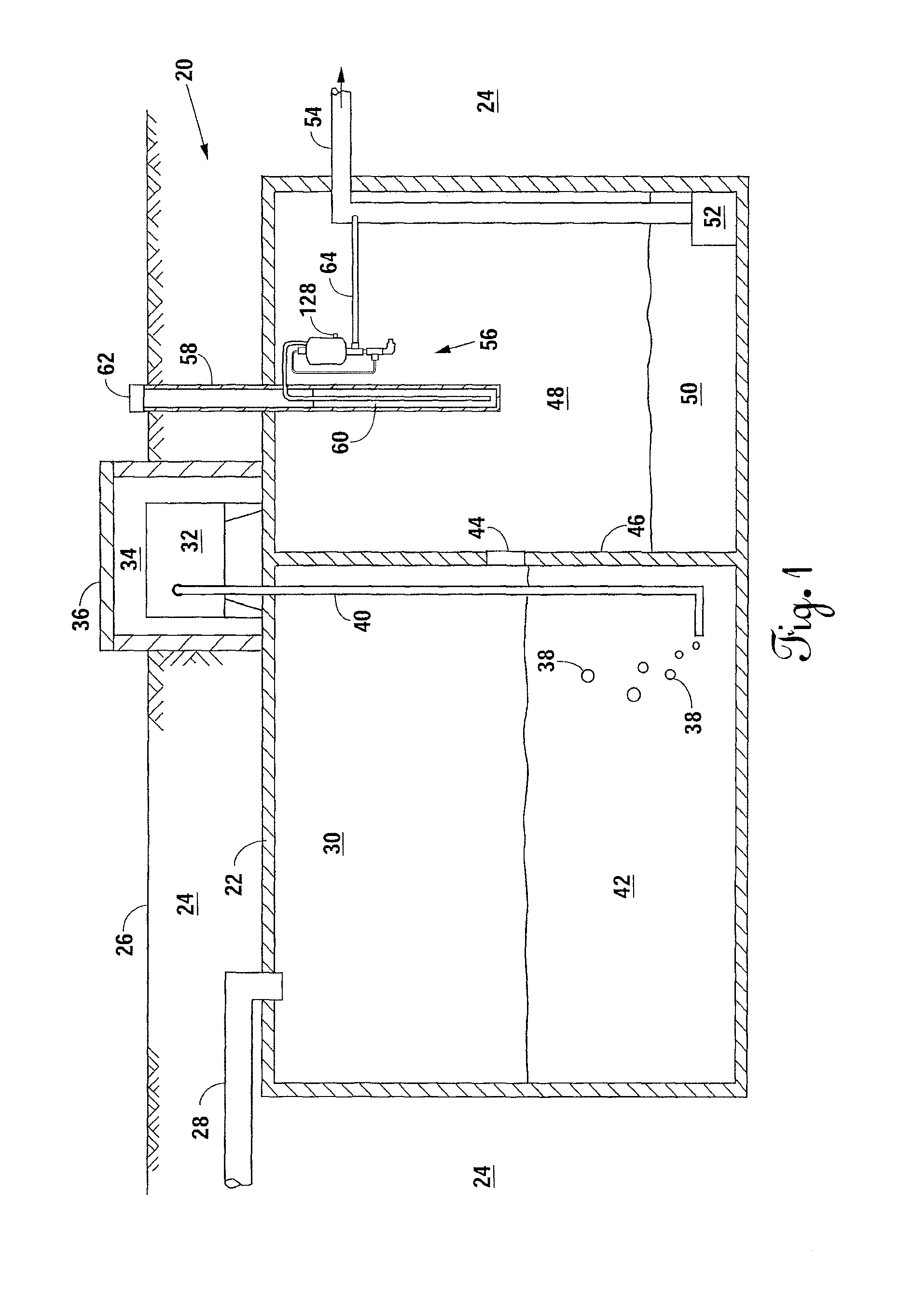
[0019]FIG. 1 discloses an aerobic treatment system 20 incorporating the present invention and comprising a storage tank 22 buried in the earth 24 beneath a ground surface 26. During operation, sewage flows from an on-site facility, such as a residence, through a sewage pipe 28 into the storage tank 22 and, more specifically, into an aeration chamber 30. Because aerobic bacteria present in the aeration chamber 30 require oxygen to break down the sewage into simple compounds, an air compressor 32, which is contained within a compressor chamber 34 and accessible by removing a cover 36, continuously forces air 38 into the aeration chamber 30 through an aeration hose 40. The sewage breakdown from this aerobic process produces primarily liquid wastewater 42 that flows from the aeration chamber 30 through an opening 44 in a baffle 46 and into a holding chamber 48 as effluent 50. After proper dosing with a disinfectant, a pump 52 moves the effluent through a discharge pipe 54 and into the s...


PUM

PropertyMeasurementUnit
volumeaaaaaaaaaa
pressureaaaaaaaaaa
liquidaaaaaaaaaa

Abstract

A vacuum-actuated liquid chlorine dispenser for use in an aerobic treatment system. Effluent is diverted from a discharge pipe in an aerobic treatment system into an inlet of a venturi chamber. The resulting pressure differential resulting from effluent flowing through the venturi chamber is communicated to a dosage container, which results in disinfectant flow from a reservoir into the dosage container until the volume of disinfectant contained by the dosage container causes a pressure control device, such as a float valve, to inhibit further pressure communication. Thereafter, the accumulated disinfectant within the dosage container egresses through a disinfectant outlet that may include a flow regulation device such as a drip emitter or check valve. The present invention allows for more regular dosing of known and accurate disinfectant amounts following each pumping cycle of the aerobic treatment system.

Description

CROSS-REFERENCES TO RELATED APPLICATIONS[0001]This original nonprovisional application claims the benefit of U.S. provisional application No. 60 / 971,365, filed Sep. 11, 2007 and entitled “NG 300 V Chlorine Dispenser,” and which is incorporated by reference herein.STATEMENT REGARDING FEDERALLY SPONSORED RESEARCH OR DEVELOPMENT[0002]Not applicable.BACKGROUND OF THE INVENTION[0003]1. Field of the Invention[0004]The present invention relates generally to an apparatus for use with aerobic treatment systems. More specifically, the invention relates to a vacuum-actuated liquid disinfectant dispenser for treating sewage wastewater prior to discharging effluent into the environment.[0005]2. Description of the Related Art[0006]Aerobic treatment systems treat wastewater using natural processes that require oxygen. Bacteria work to break down and digest the wastewater inside the aerobic treatment unit. Because these bacteria flourish in high-oxygen environments, aerobic treatment systems requir...

Claims


Application Information

Patent Timeline
Patent Type & Authority Patents(United States)
IPC IPC(8): C02F9/04
CPCC02F1/686C02F3/1294C02F1/76C02F3/12Y02W10/10
Inventor YANDELL, CECIL
Owner D I R MFG & SUPPLIES
Why Eureka
Try Eureka