Water jacket spacer

a technology of spacers and water jackets, which is applied in the direction of engine cooling apparatus, liquid cooling, cylinders, etc., can solve the problem that the position of water jacket spacers in water jackets cannot be determined easily, and achieve the effect of maximizing the load caused by the urging force of leaf springs

Inactive Publication Date: 2017-01-26
TOYOTA JIDOSHA KK +1
View PDF13 Cites 19 Cited by
  • Summary
  • Abstract
  • Description
  • Claims
  • Application Information

AI Technical Summary

Benefits of technology

[0018]With the above configuration, when the abutment portion of the leaf spring abuts against the inner wall of the water jacket, the leaf spring is flexed to the most, and the load caused by the urging force of the leaf spring is maximized. Furthermore, the abutment portion of the leaf spring abuts against the inner wall of the water jacket at a position further than the center of the water jacket spacer in a direction opposite to the insertion direction. Thus, the load caused by the urging force of the leaf spring is maximized when the water jacket spacer is inserted in the water jacket by half or more than half the length of the water jacket spacer. This further reduces the insertion load when the insertion depth of the water jacket spacer is small.

Problems solved by technology

However, when the water jacket spacer is applied to the water jacket of the cylinder block having an open-deck structure, the position of the water jacket spacer in the water jacket cannot be determined easily.

Method used


Image

  • Water jacket spacer
  • Water jacket spacer
  • Water jacket spacer

Examples


first embodiment

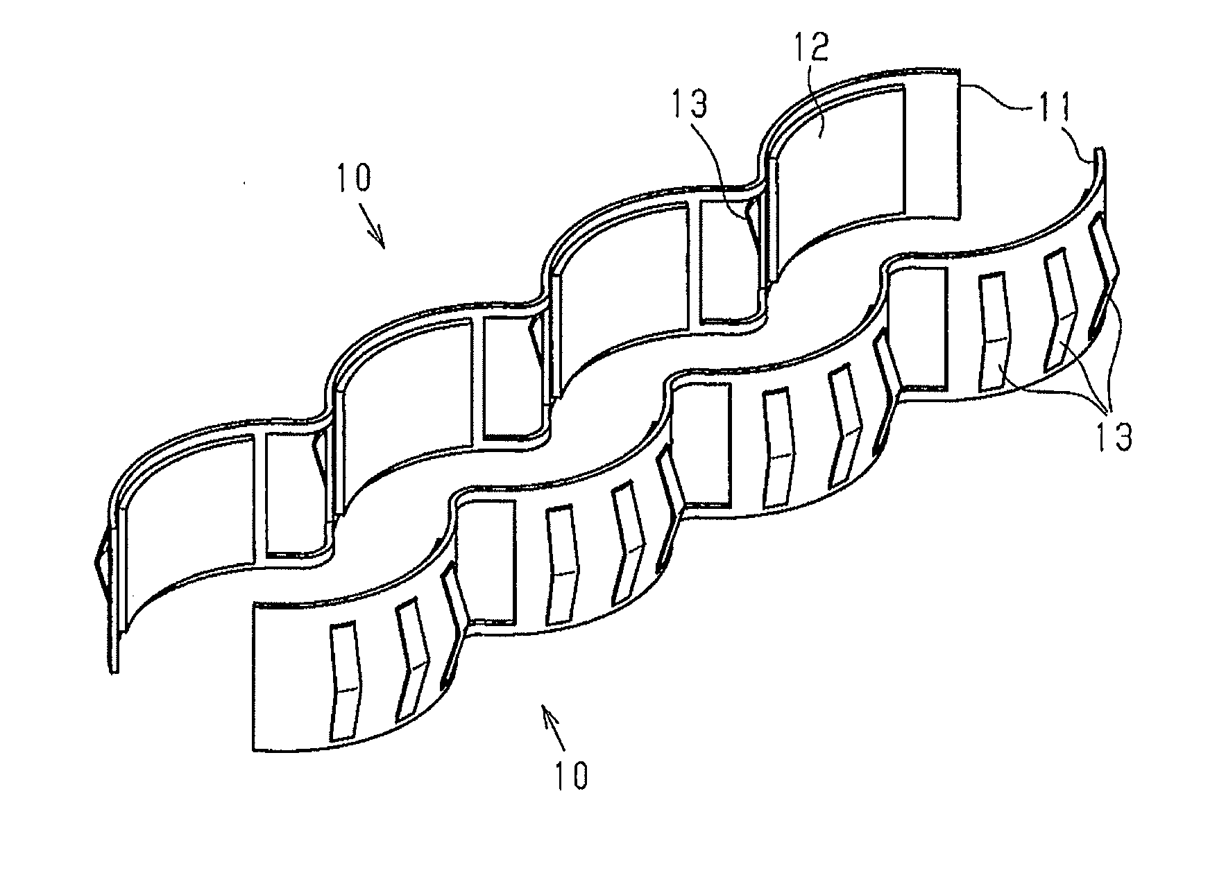
[0027]A water jacket spacer according to a first embodiment of the present invention will now be described with reference to FIGS. 1 to 5(c).

[0028]As shown in FIG. 1, water jacket spacers 10 are used in a pair. Each water jacket spacer 10 includes a metal plate-shaped holder 11 and expansion members 12, which are secured to the holder 11. The water jacket spacer 10 is configured by coupling four expansion members 12 with one another using the holder 11. The expansion members 12 are thermal expansion members, which expand upon receipt of heat. Each holder 11 includes leaf springs 13 on the other side of the holder 11 from the side on which the expansion members 12 are provided. Three leaf springs 13 are provided at a position corresponding to each expansion member 12.

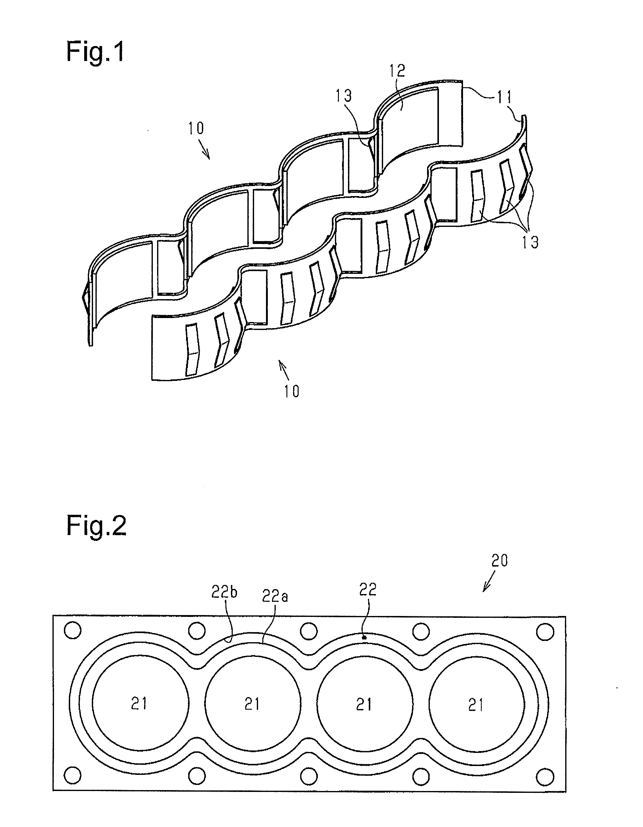
[0029]FIG. 2 shows a cylinder block 20, which includes a water jacket 22 to which the water jacket spacers 10 are applied. The cylinder block 20 is for an in-line four-cylinder internal combustion engine and includes fou...

second embodiment

[0051]A water jacket spacer according to a second embodiment of the present invention will now be described with reference to FIGS. 6 to 8.

[0052]In a water jacket spacer 110 of the second embodiment, the shape of a leaf spring 113 differs from that of the leaf spring 13 of the first embodiment. The same reference numerals are given to those components that are common to the first embodiment, and detailed explanations are omitted.

[0053]FIG. 6 shows a state in which the expansion member 12 is expanded after the water jacket spacer 110 is inserted in the water jacket 22. Arrow in FIG. 6 shows the insertion direction of the water jacket spacer 110.

[0054]As shown in FIG. 6, the leaf spring 113 includes a proximal end at the edge section of the water jacket spacer 110 from which the water jacket spacer 110 is inserted into the water jacket 22. The leaf spring 113 also includes an abutment portion 113a, which abuts against the second wall 22b. The leaf spring 113 extends from the proximal ...


PUM


Abstract

A water jacket spacer is inserted into a water jacket. The water jacket spacer includes an expansion member, a plate-shaped holder to which the expansion member is fixed, and a leaf spring that abuts the inner wall of the water jacket. The leaf spring projects from a face on the holder on the side opposite of the expansion member. The holder curves to match the shape of the water jacket. The position of the water jacket spacer in the water jacket is maintained by the biasing force of the leaf spring.

Description

TECHNICAL FIELD[0001]The present invention relates to a water jacket spacer.BACKGROUND ART[0002]Water jacket spacers have been proposed that optimize the flow of water in a water jacket and improve temperature distribution on a cylinder wall. Such a water jacket spacer is inserted in the water jacket of a cylinder block to be used.[0003]Patent Document 1 discloses a water jacket spacer that includes an expansion member formed of water-swelling cellular rubber, which expands when it comes into contact with a coolant. The water jacket spacer disclosed in Patent Document 1 is inserted in the water jacket through a hole in the upper surface of the cylinder block. When the water jacket spacer is inserted in the water jacket, the expansion member expands in the water jacket. Thus, the water jacket spacer is secured in the water jacket. In this case, the water jacket spacer needs to be held in a predetermined position until the water jacket spacer is secured by the expansion of the expansi...

Claims


Application Information

Patent Timeline
Patent Type & Authority Applications(United States)
IPC IPC(8): F02F1/16F01P3/02F02F1/36
CPCF02F1/166F01P2003/021F01P3/02F02F1/36F02F1/14
Inventor KARITA, TAKASHITAKENAKA, KAZUNARISUGIMOTO, SHINSUKEYOSHIMURA, AKIHIRONISHIO, KAZUAKI
Owner TOYOTA JIDOSHA KK
Why Eureka
Try Eureka