Alternating Flow Column Chromatography Apparatus and Method of Use

a chromatography apparatus and alternating flow technology, applied in the field of chromatography columns, can solve the problems of unacceptably low radioactive concentration of sup>99m/sup>tc-eluate solution for use in most radiopharmaceutical diagnostic procedures, poor adsorption-desorption kinetics, etc., to achieve maximum sharpness, increase the purification effect of the purification column, and maximize the loading capacity of the separation column

Active Publication Date: 2020-02-20
LE VAN SO +1
View PDF0 Cites 1 Cited by
  • Summary
  • Abstract
  • Description
  • Claims
  • Application Information

AI Technical Summary

Benefits of technology

[0027]An object of the present invention is a new chromatographic apparatus (alternating flow chromatography apparatus) and new separation-purification method of use (alternating flow chromatography met

Problems solved by technology

The low 99Mo adsorption capacity and/or poor adsorption-desorption kinetics of available generator-column packing materials are challenging the use of low specific activity 99Mo, specifically because a large column is required to produce a generator of acceptable activity.
So large eluent volumes required to elute 99mTc-nuclide from the generator then cause the radioactive concentration of the 99mTc-eluate solution to become unacceptably low for use in most radiopharmaceutical diagnostic procedures.
This challenging issue arises for the manufacturing technology of different radionuclide generators as well.
This situation is the cause of unwanted large volume and dilute concentration of the target nuclide eluate produced from the DFCC method-based 99mTc generators.
This unfavourable issue arises for the manufacturing technology of different radionuclide generators as well.
Unfortunately, all of these short-lived (half-life less than 2 hours) positron-emitting radionuclides are only available from onsite, expensive cyclotrons operating in a handful of major hospitals.
However, the 5 mL dilute HCl solution required for 68Ga elution and the unavoidably high metallic ion contamination makes the

Method used


Image

  • Alternating Flow Column Chromatography Apparatus and Method of Use
  • Alternating Flow Column Chromatography Apparatus and Method of Use
  • Alternating Flow Column Chromatography Apparatus and Method of Use

Examples


first embodiment

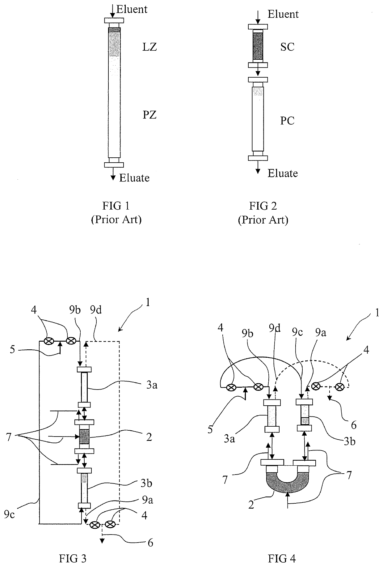
[0075]an alternating flow column chromatography (AFCC) apparatus for the chromatographic separation and chromatographic purification of the ionic radionuclide components and chemical components of size <2.5 nm (<25 Å) soluble in an aqueous solution is depicted schematically in FIG. 3.

[0076]The composition to be separated is a mixture of ionic desired (target or product) components, ionic product-generating components and ionic contaminant components (including the breakthrough of ionic product-generating components leachable from the separation and purification columns into eluate flow). The components (species) of the composition to be separated are ionic and / or non-ionic molecules of size <2.5 nm soluble in an aqueous solution. The product component may be generated from a product-generating component as a result of chemical, biochemical and nuclear (radiochemical) decomposition processes. The decomposition process may be an in-situ process occurring inside of the separation colum...

third embodiment

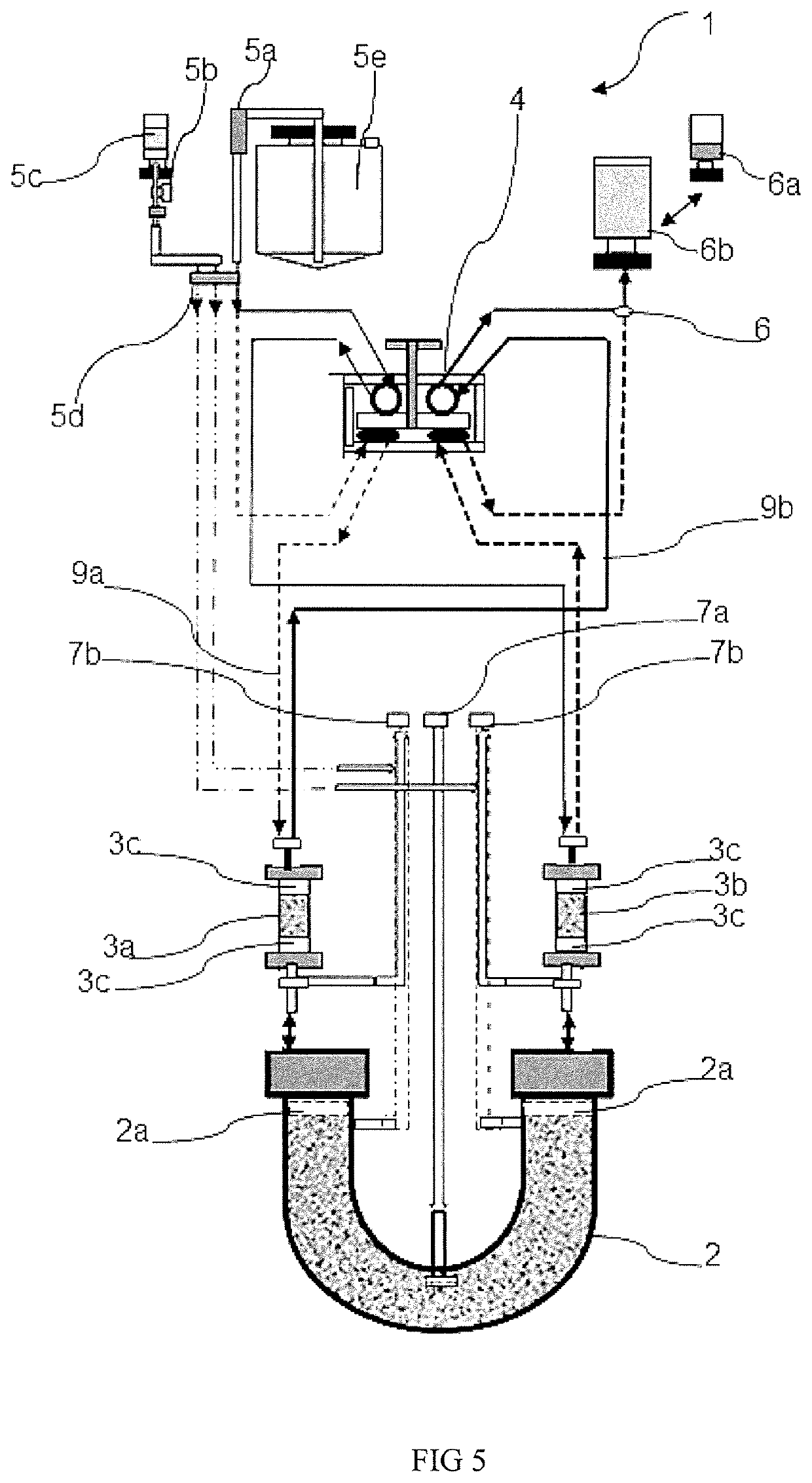
[0081]In order to better describe the invention a more detailed illustration of an alternating flow column chromatography (AFCC) apparatus is shown in FIG. 5. Suitably the AFCC apparatus is setup in the format of an integrated device, preferably in a format of benchtop device operated by a limited vacuum driving force for eluent / eluate liquid flow communication without using differential pressure controllers.

[0082]As with the first and second embodiments, the apparatus 1 consists of a separation column 2, a pair of purification columns 3a, 3b, and an alternating flow valve 4. In the third embodiment, the separation column 2 has a ‘U’ shape, although it could also be configured with an ‘I’ shape. The alternating flow valve 4 is operated to reverse the direction of the eluent flow from feed eluent port 5 to eluate collection port 6 through the columns 2, 3a, 3b. A mixture of species to be separated may be loaded through a central separation column loading port 7a or through loading po...

example 1

od Based 68Ga-Generator Using High Specific Activity 68Ge-Source (Operation Per FIG. 13a)

[0183]This example of the present invention relates to the 68Ga generators produced based on the nano-crystalline sorbent ZT-11 (Adsorption capacity: 1.3 mg Ge / g sorbent) and the multifunctional sorbent ISOSORB-MOX-HP (Adsorption capacity: 3.0 mg Ge / g), which are specified in the patent applications WO 2011 / 106847 A1 and WO 2015 / 039170A1, respectively. 68Ge-source of high specific activity 1.6 mCi 68Ge / μg Ge was used for loading the generator column.

[0184]These sorbents are in solid particulate form, so that the generator columns contain a packed bed of the particulate sorbent. Both sorbents have a much higher affinity for 68Ge than for 68Ga so that 68Ga is preferentially eluted from the sorbent while the majority, preferably substantially all, of the 68Ge is retained on the sorbent. Typically both sorbents ZT-11 and ISOSORB-MOX-HP are such that the breakthrough percentage of 68Ge is less than 1...


PUM


Abstract

An alternating flow column chromatography apparatus comprising a ‘U’ shaped or T shaped separation column including at least one loading port for loading of components for separation, a first purification column in fluid communication with one end of the separation column and a second purification column in fluid communication with another end of the separation column, at least one eluent input port, an eluate output port and an alternating flow valve in fluid communication with the primary eluent input port, the eluate output port, the first purification column and the second purification column wherein, when operated, the alternating flow valve reverses the flow of eluent through the purification columns and the separation column. Also a method of using the apparatus. A benefit of the apparatus and method is more efficient operation compared to existing direct flow column chromatography apparatuses.

Description

TECHNICAL FIELD[0001]This invention relates to radionuclide generators and methods for the manufacture of radionuclides. In particular, the invention relates to a chromatography column that is useful in a radionuclide generator and other applications.BACKGROUND OF THE INVENTIONRadionuclide Generators[0002]Medical diagnostic and therapeutic applications of radioisotopes have long been recognised by the medical community and are being used to help millions of patients throughout the world. Today the diagnostic imaging and therapeutic application in advanced nuclear medicine using different kinds of radiopharmaceuticals and radioisotopes, such as 99mTc, 81mKr, 68Ga, 44Sc, 82Rb, 188Re, 213Bi, 90Y, 18F, 131I, 123I, 124I, 11C, 15O, 64Cu, 89Zr, 51Cr, . . . is most widely known. Among these 99mTc, 81mKr, 68Ga, 44Sc, 82Rb, 188Re, 213Bi and 90Y (called daughter nuclide) are produced from the radionuclide generators loaded with their parent radionuclide 99Mo, 81Rb, 68Ge, 44Ti, 82Sr, 188W, 225A...

Claims


Application Information

Patent Timeline
IPC IPC(8): B01D15/22B01D15/18G01N30/46G21G1/00G01N30/60
CPCG01N30/6052G01N2030/385G01N30/46B01D15/22G01N2030/8809B01D15/1864G21G1/0005G01N30/38B01D15/18
Inventor LE, VAN SOLE, MINH KHOI
Owner LE VAN SO
Why Eureka
Try Eureka