Transformer Station, Method and Apparatus for a Transformer Station

a transformer station and transformer technology, applied in the field of transformer stations, can solve the problems of unnecessarily high installation and acquisition costs of transformers, unnecessary space requirements, and inadequate consideration of cooling by wind by relevant design standards, and achieve the effect of maximizing the cooling effect of wind flow, easy design, installation and operation

Active Publication Date: 2019-10-10
INNOGY SE
View PDF0 Cites 1 Cited by
  • Summary
  • Abstract
  • Description
  • Claims
  • Application Information

AI Technical Summary

Benefits of technology

[0018]An air deflecting element, in particular, in the form of an air deflecting plate, can comprise any shape. In particular, it has a flat structure. Preferably, the air deflecting plate can have a plane (or flat) side profile or a curved side profile. It is also possible to combine a plurality of air deflecting plates to create a pre-defined side profile of an air deflecting unit. The air deflecting plate can, in particular, be adapted to the dimensions of the transformer station and/or to the dimensions and/or position of the transformer cooling unit. An even better cooling can be provided in a simple way.
[0019]In principle, according to a preferred embodiment, the at least one air deflecting unit can be a static unit. Such a unit can be easily designed, installed and operated. According to a further embodiment of a transformer station in accordance with the application, the air deflecting unit can be an air deflecting unit which can be (dynamically) adjusted to the current wind conditions. In other words, such an air deflecting units allows the provision of different air ducts, for example, depending on a current wind

Problems solved by technology

The reason for this is that the relevant design standard does not (sufficiently) take cooling by wind into account.
This leads to over dimensioning, unnecessary space requirements on the t

Method used


Image

  • Transformer Station, Method and Apparatus for a Transformer Station
  • Transformer Station, Method and Apparatus for a Transformer Station
  • Transformer Station, Method and Apparatus for a Transformer Station

Examples


Embodiment Construction

[0043]In the figures, the same reference signs are used for the same elements.

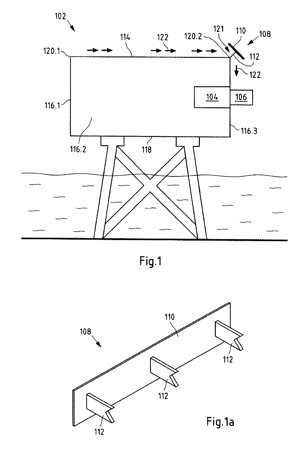
[0044]FIG. 1 shows a schematic view of a first embodiment of a transformer station 102 according to the present application. The transformer station is an offshore transformer station 102 of an (not shown) offshore wind energy system and offshore wind energy park, respectively. The offshore wind energy system can preferably comprise a plurality of offshore wind turbines connected to the offshore transformer station 102 and offshore substation 102, respectively, via submarine cables. In particular, a submarine cable is configured to transmit the electrical energy generated by a wind turbine to the next wind turbine or to the offshore transformer station 102.

[0045]In particular, a plurality of wind turbines may be connected in series in several strings. For example, eight strings each with six wind turbines can be provided. An end of a string can be electrically connected to the offshore transformer station ...


PUM


Abstract

A transformer station, in particular, an offshore transformer station including at least one transformer and at least one transformer cooling unit arranged on at least one side wall of the transformer station or a roof of the transformer station and configured to cool the at least one transformer. The transformer station also includes at least one air deflecting unit arranged on at least one roof edge of the transformer station and/or at least one air deflecting unit arranged on at least one side edge of the transformer station. The air deflecting unit is arranged such that an air movement is deflectable in the direction of the transformer cooling unit.

Description

CROSS-REFERENCE TO RELATED PATENT APPLICATIONS[0001]This patent application is a continuation of PCT / EP2017 / 078733, filed Nov. 9, 2017, which claims priority to German Application No. 10 2016 125 375.8, filed Dec. 22, 2016, the entire teachings and disclosure of which are incorporated herein by reference thereto.FIELD[0002]The invention relates to a transformer station, in particular, an offshore transformer station, comprising at least one transformer and at least one transformer cooling unit arranged on at least one side wall or roof of the transformer station and configured to cool the at least one transformer. In addition, the invention relates to a method and an apparatus for a transformer station.BACKGROUND[0003]Nowadays wind energy systems are increasingly used for the production of electrical energy. So called offshore wind energy systems are preferred. The reason for this is that compared to onshore wind energy systems, the expected average wind speed and thus the expected ...

Claims


Application Information

Patent Timeline
IPC IPC(8): H01F27/08H01F27/02
CPCH01F27/025H01F27/085H02B1/56H02B5/00
Inventor RUNGE, JÖRN
Owner INNOGY SE
Why Eureka
Try Eureka