
Torsional damping device for a motor vehicle transmission system

Inactive Publication Date: 2017-01-26
VALEO EMBRAYAGES SAS
View PDF1 Cites 1 Cited by
  • Summary
  • Abstract
  • Description
  • Claims
  • Application Information

AI Technical Summary

Benefits of technology

The invention aims to provide a simple and effective solution to prevent the pendulum support from moving in the axial direction during operation. This is achieved by using an axial stop and a complementary surface on the radially inner periphery of the hub. This solution is economical and efficient.

Problems solved by technology

A phasing member of this kind exhibits decreased stability because it is centered essentially by the elastic members.

Method used


Image

  • Torsional damping device for a motor vehicle transmission system
  • Torsional damping device for a motor vehicle transmission system
  • Torsional damping device for a motor vehicle transmission system

Examples


Embodiment Construction

)

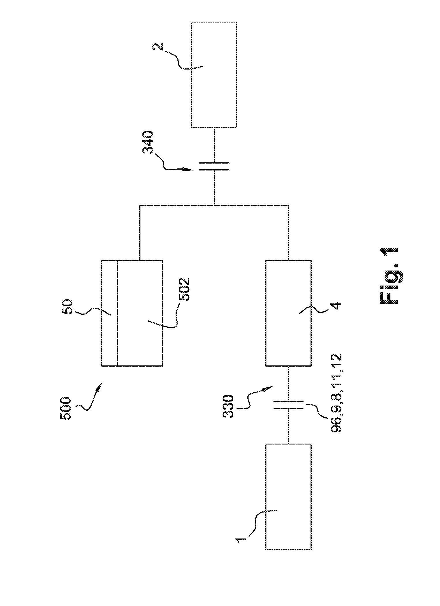
[0049]FIG. 1 illustrates a transmission assemblage disposed between a combustion engine 1 and a gearbox 2, according to an embodiment of the invention. The transmission assemblage has a first friction clutch 330, a torsional damping device 4, an electric machine 500 comprising a stator 501 and a rotor 502, and a second friction clutch 340.

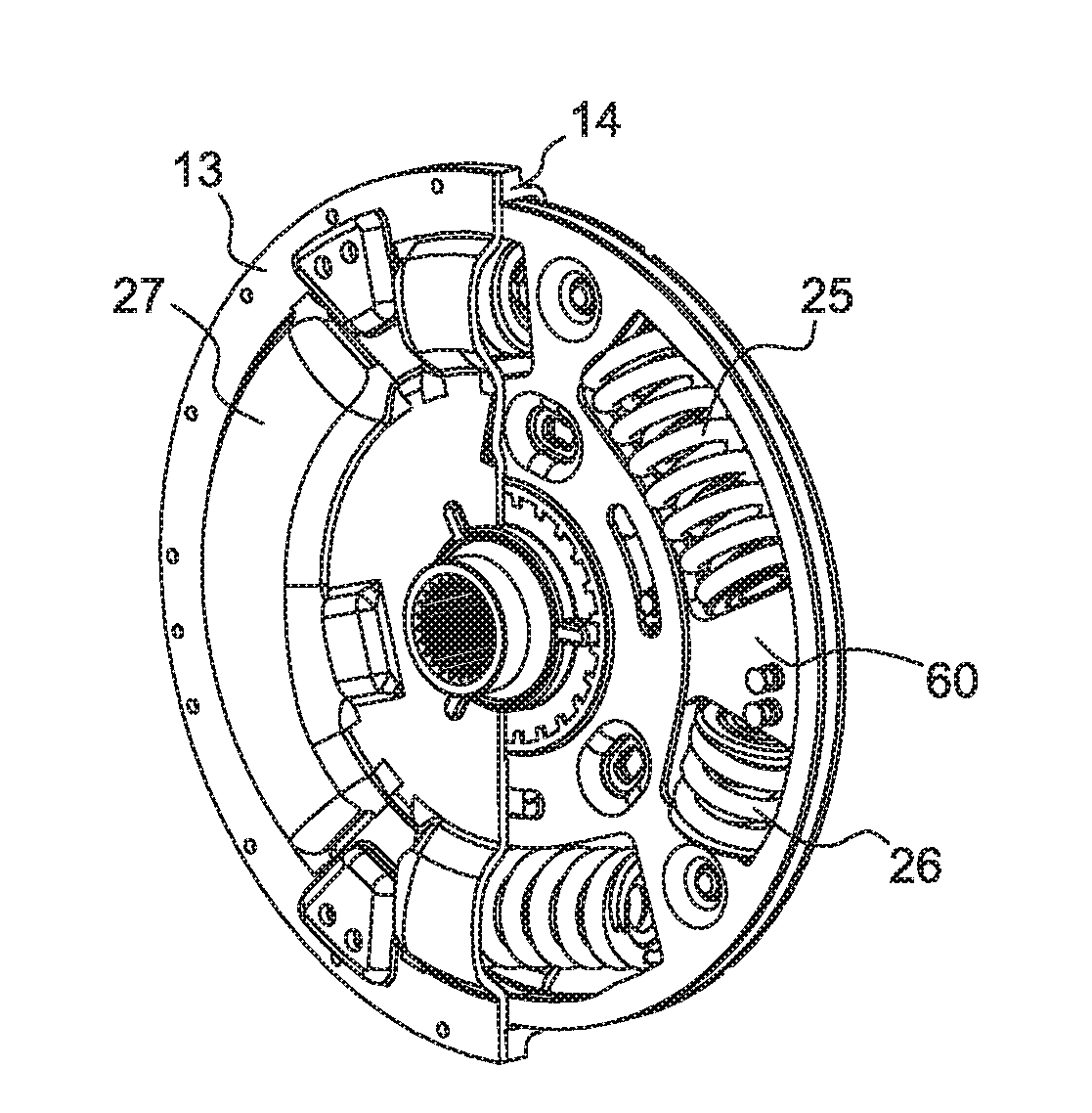
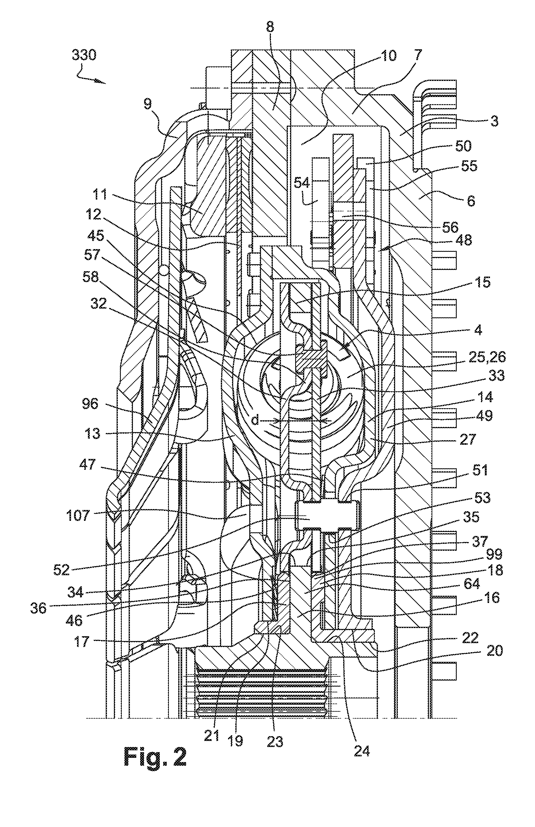
[0050]FIG. 2 illustrates first friction clutch 330 associated with torsional damping device 4. First friction clutch 330 is connected to an inertial wheel 3. Inertial wheel 3 has a first annular region 6 extending radially, and a cylindrical region 7 extending axially toward to the rear from the outer periphery of first annular region 6. A second cylindrical region 8 and an annular cover 9 are fastened on cylindrical region 7. First annular region 6, cylindrical region 7, and second annular region 8 define an annular chamber 10.

[0051]Inertial wheel 3 also has orifices (not depicted) configured in first annular region 6. Fastening screws (not depic...


PUM


Abstract

A torsional damping device (4) having:a first movable element (13, 14) and a second movable element (15, 16), coaxial and rotationally movable around an axis X;a central hub rotationally coupled to the second element;at least one group of elastic members (25, 26) acting against rotation of the first element and second element with respect to one another;a phasing member (32, 33) constituted by two parts (32, 33), for arranging the elastic members of that group in series so that the elastic members of each group deform in phase with one another; anda pendulum damper (48) rotationally connected to the phasing member, the phasing member being centered on the central hub by means of the pendulum support member.

Description

CROSS-REFERENCE TO RELATED APPLICATIONS AND CLAIM TO PRIORITY[0001]This application is related to Patent Application No. 1557110 filed Jul. 24, 2015 in France, the disclosure of which is incorporated herein by reference and to which priority is claimed.FIELD OF THE INVENTION[0002]The present invention relates to a torsional damping device, in particular for a motor vehicle transmission system.BACKGROUND OF THE INVENTION[0003]In such an application the torsional damping device can be integrated into a torsional damping system of a clutch capable of selectively connecting the combustion engine to the gearbox, in order to filter vibrations due to irregularities of the engine.[0004]As a variant, in such an application the torsional damping device can be integrated into a dual mass flywheel, into a friction disk of the clutch, or into a hydrodynamic torque converter.[0005]The invention also relates to a transmission assemblage for a motor vehicle of the hybrid type, in which an electric ...

Claims


Application Information

Patent Timeline
IPC IPC(8): F16F15/134B60L50/16
CPCF16F15/134F16F15/1232F16F15/26F16F15/28F16F2222/08F16F15/13492F16F15/145Y02T10/72
Inventor LEBAS, GILLESVERHOOG, ROELLAFORGE, THIBAULTCAILLERET, FRANCKCOMMEINE, EMMANUEL
Owner VALEO EMBRAYAGES SAS
Learn More