Device for Analysis of Synthetic Rope or Cable, and Method of Use

Active Publication Date: 2017-01-26
HER MAJESTY THE QUEEN & RIGHT OF CANADA REPRESENTED BY THE MIN OF NATURAL RESOURCES
View PDF4 Cites 18 Cited by
  • Summary
  • Abstract
  • Description
  • Claims
  • Application Information

AI Technical Summary

Benefits of technology

[0012]a lay length calculator or display that calculates or displays a distance along the synthetic rope of one or more of the detected

Problems solved by technology

For such applications, ropes may have considerable length and must carry considerable loads, including the weight of the ropes themselves in the sections between the conveyances and the mine hoists at the surface (and underground as well) and used for their deployment.
The costs to replace ropes can be very significant, and yet timely replacement is imperative to avoid excessive rope wear and rupture.
Localized faults, wear, corrosion, core deterioration, strand breakage etc. may all cause increased lay length.
In general, if the lay length of a rope or cable and the like changes beyond defined limits, or if it changes locally, this may indicate potential failure of the rope, and the requirement for rope replacement.
However, compared to wire ropes, it can be more difficult to assess local

Method used


Image

  • Device for Analysis of Synthetic Rope or Cable, and Method of Use
  • Device for Analysis of Synthetic Rope or Cable, and Method of Use
  • Device for Analysis of Synthetic Rope or Cable, and Method of Use

Examples


Example

Example 1

Non-Destructive Test Methods for High-Performance Synthetic Rope

[0140]Interest in high performance-synthetic ropes for mine hoisting has increased as mine operators pursue resources at greater depths. One limiting factor for hoisting capacity is the self-weight of steel wire used as the hoist rope. The significantly higher strength to weight ratio of synthetic rope offers the attractive alternative to enable hoisting a larger payload with a similar size rope and hoisting plant.

[0141]Due to the critical nature of hoist rope service, frequent and reliable inspection methods are required and regulated. Visual inspection and a variety of electromagnetic methods are used to monitor in-situ the integrity of presently used wire ropes for mine hoisting. Wire ropes have been used for decades in hoisting applications and the data acquired through nondestructive test (NDT) methods can be correlated with a wealth of data and experience to ensure safe and successful operation.

[0142]For ...

Example

Example 2

Scaled CBOS Test Results and MFL Device Output

Introduction

[0158]As easily accessible resources near the surface are depleted, the mining industry must go deeper and deeper to reach materials. The current system of steel wire ropes has limitations. At a depth of more than 7,500 feet a steel wire can no longer be used and a second shaft with a second hoist and wire must be installed. The two stage process greatly slows down the extraction of materials and contributes to increased operations costs. This along with many other factors makes synthetic ropes an economically viable alternative to steel wire at greater depths.

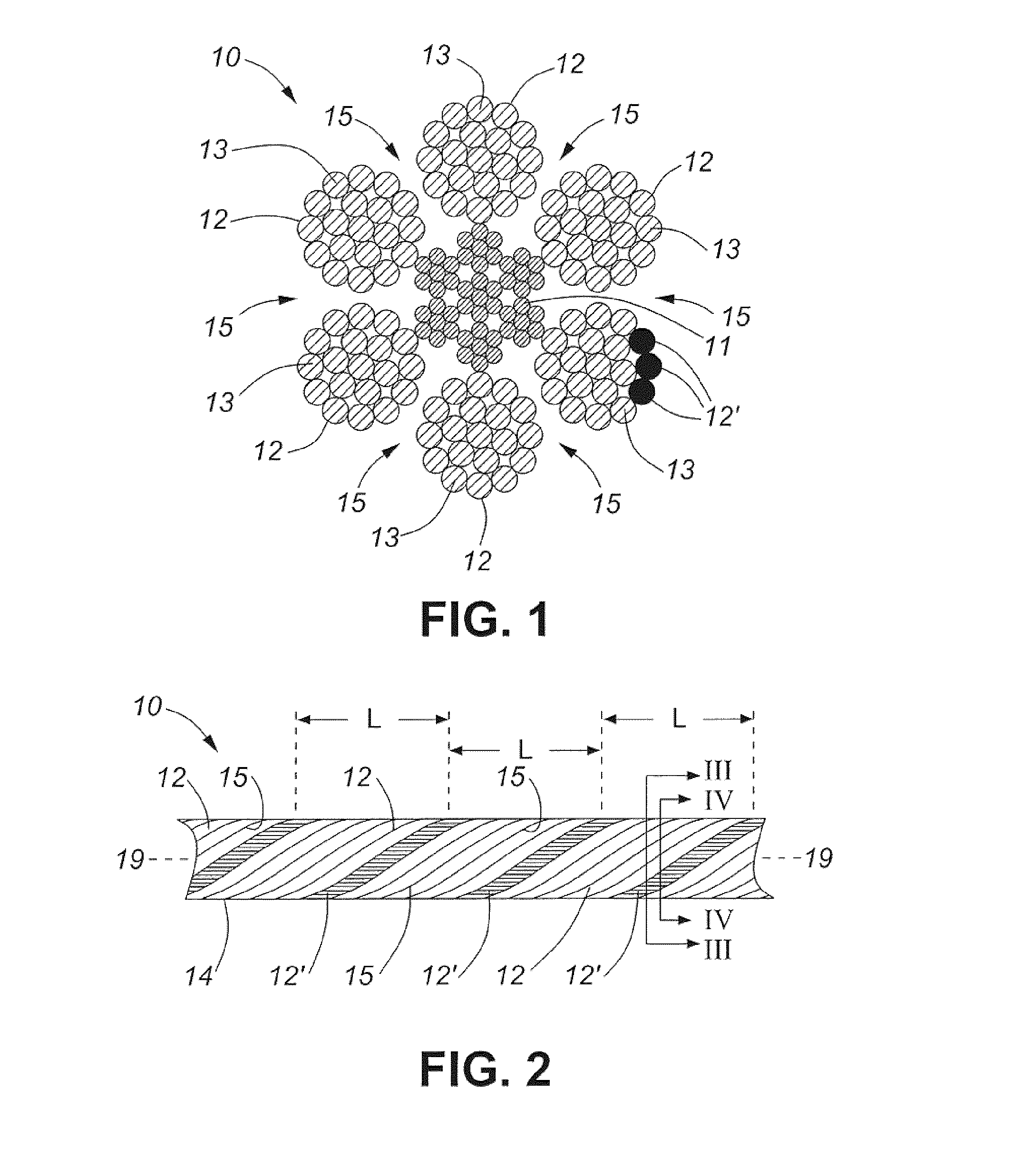
[0159]Synthetic ropes for mine hoisting are being developed out of an aramid fiber, Twaron. This fiber was chosen for its high strength-to-weight ratio and high elastic modulus. These properties allow a similar diameter and stiffness rope to that of the current steel wire with one-fifth the weight. The fiber also has the advantage of being heat, cut and chemica...


PUM


Abstract

Disclosed are methods and apparatuses for analysis of synthetic ropes, cords, slings, cables and belts (collectively termed “ropes”) including but not limited to ropes for bearing loads as well as fibre optic cables. The ropes are provided with one or more elements for magnetic detection, wherein the magnetic detection elements each comprise a metal fibre or an appropriately treated synthetic fibre. The methods and apparatuses encompass detection of induced or residual magnetism or magnetic flux in the magnetic detection element(s), to sense for example lay length and/or damage, breakage or wear of the magnetic detection element(s), indicative of the condition of the rope.

Description

FIELD OF THE INVENTION[0001]This invention relates to the field of analysis and / or testing / monitoring of synthetic ropes, cables, slings, cords and belts. In particular the invention permits analysis of the integrity and load capacity of ropes, cables, slings, cords and belts with industrial applications, such as in mine hoisting operations. In other embodiments, the invention permits analysis of the integrity and function of fibre optic cables and the like.BACKGROUND TO THE INVENTION[0002]Ropes, cables and the like are used extensively for many purposes such as ropeways, cable cars, ski lifts, chairlifts, elevators, and military applications, but are of particular importance in the mining industry where the Intent is to use these for raising and lowering conveyances carrying personnel, equipment, material, waste and ore in underground operations, such as between the mining accesses and the surface. For such applications, ropes may have considerable length and must carry considerabl...

Claims


Application Information

Patent Timeline
IPC IPC(8): G01B7/04D07B1/14G01N27/90
CPCG01B7/046D07B2301/5536D07B1/145G01N27/9026G01N27/83D07B2301/555G01N27/82G01N27/90G01N27/9006G01N27/9013G01N27/904D07B1/24
Inventor OUELLETTE, SYLVAIN
Owner HER MAJESTY THE QUEEN & RIGHT OF CANADA REPRESENTED BY THE MIN OF NATURAL RESOURCES
Why Eureka
Try Eureka