Intrusion detection system for an undersea environment

a detection system and underwater technology, applied in the field of underwater intrusion detection system, can solve the problems of high cost, high specialized, and high cost of installation of suspended optical fibers, and achieve the effect of low cos

Active Publication Date: 2017-01-26
PENN STATE RES FOUND
View PDF4 Cites 13 Cited by
  • Summary
  • Abstract
  • Description
  • Claims
  • Application Information

AI Technical Summary

Benefits of technology

[0004]This invention provides a low cost way to create and deploy, continuous, very long, intrusion detection system with a suspended raw optical fiber; instead of using a composite cable, only the raw optical fiber without any other cable components is used. By using only the raw fiber optic, a very long, continuous,...

Problems solved by technology

These suspended optical fibers usually weigh more that 10 pounds per mile and can be quite expensive due to their significant construction.
Further, the deployment of suspended optical fibers requires special fiber-optic-laying ships with high specialized, and very expensive, services.
These d...

Method used


Image

  • Intrusion detection system for an undersea environment
  • Intrusion detection system for an undersea environment
  • Intrusion detection system for an undersea environment

Examples


first embodiment

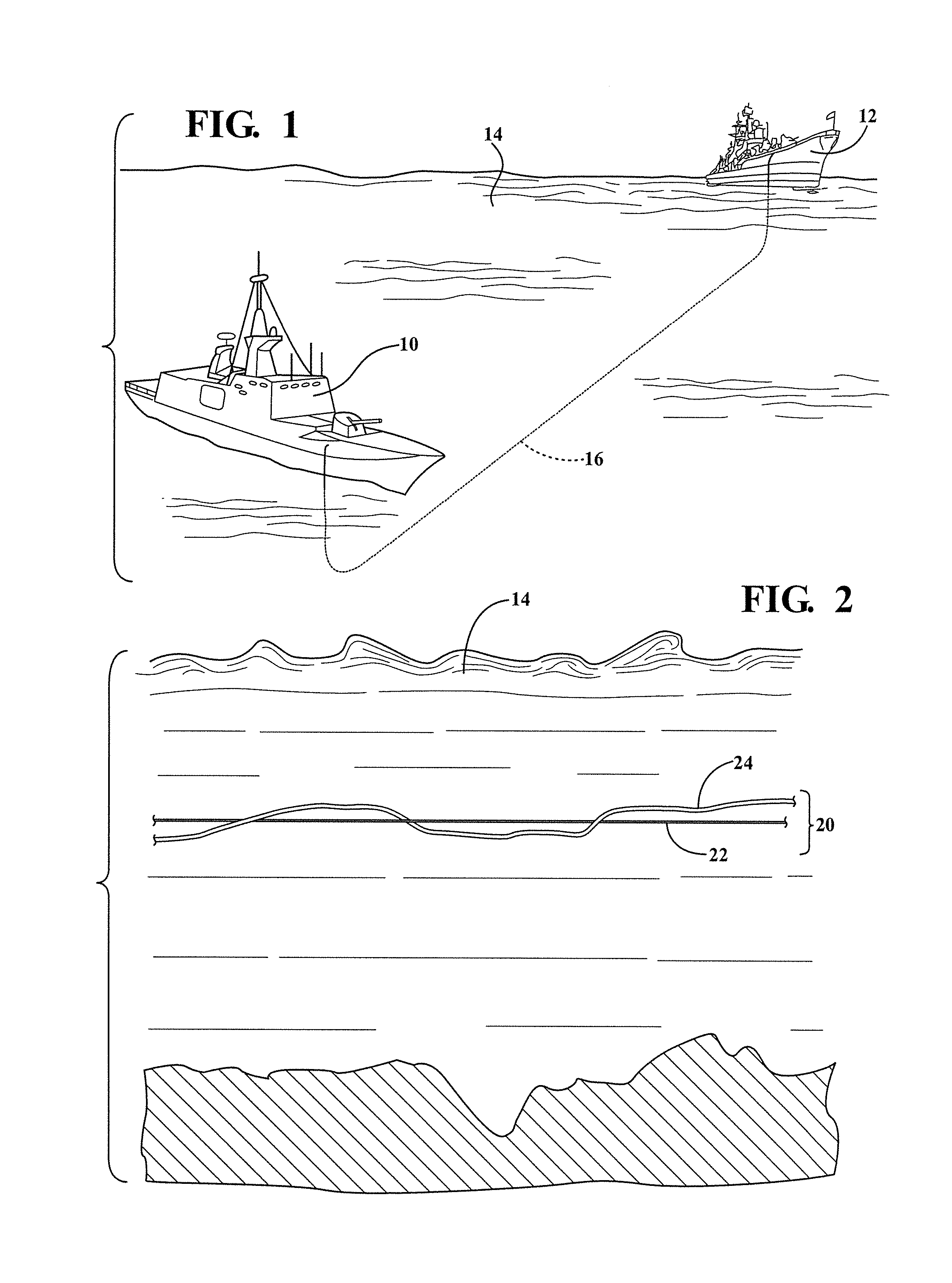
[0029]FIG. 2 illustrates the present invention wherein a composite cable assembly 20 is formed by interconnecting an elongated element 22 with an elongated supplemental filament 24. In the illustrated embodiment, the filament 24 is loosely coiled around the elongated element 22. In one example, the element 22 is an optical fiber having a negative buoyancy in the fluid environment 14. The supplemental filament 24 may be any elongated element with a positive buoyancy such that the combination of the optical fiber 22 and filament 24 create a composite assembly with a composite buoyancy that is generally neutral in the fluid environment 14.

second embodiment

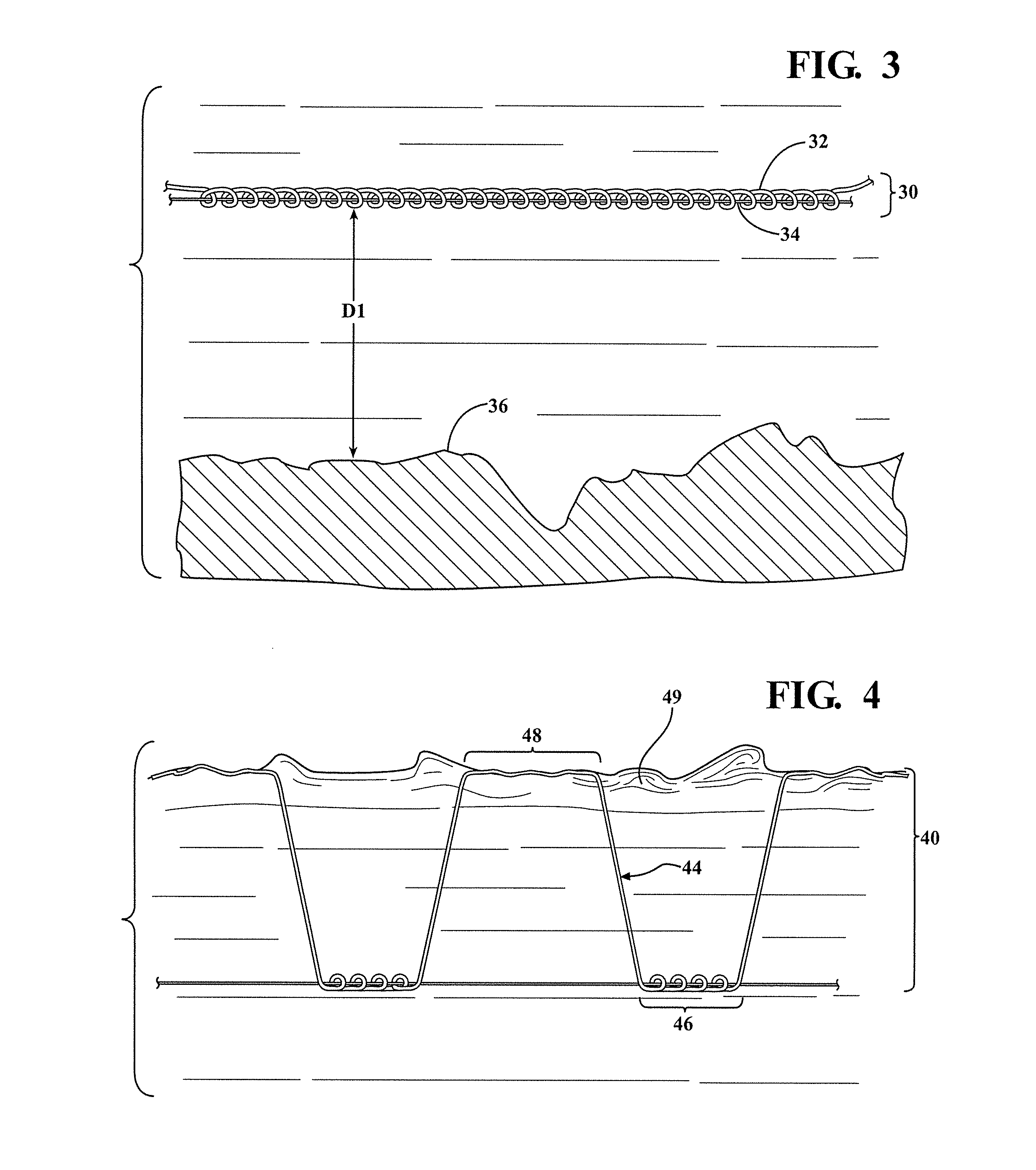
[0030]FIG. 3 illustrates the present invention in which a composite assembly 30 includes an elongated element 32 and a supplemental filament 34. As shown, the supplemental filament 34 is coiled around the elongated element 32 with significantly more coils per unit length than in FIG. 2. As will be clear to those with skill in the art, the number of coils of filament per unit length of elongated element will depend on the relevant buoyancies of the element and filament as well as other factors. The assembly 30 is shown suspended in the fluid environment at a distance D1 above a lower boundary 36 of the fluid environment. While FIGS. 2 and 3 illustrate the elongated element and supplemental filament being interconnected by coiling the supplemental filament around the elongated element, numerous other approaches to connection may be used. For example, the elongated element may be partially coiled around the filament, the filament and elongated element may be glued together or the eleme...

third embodiment

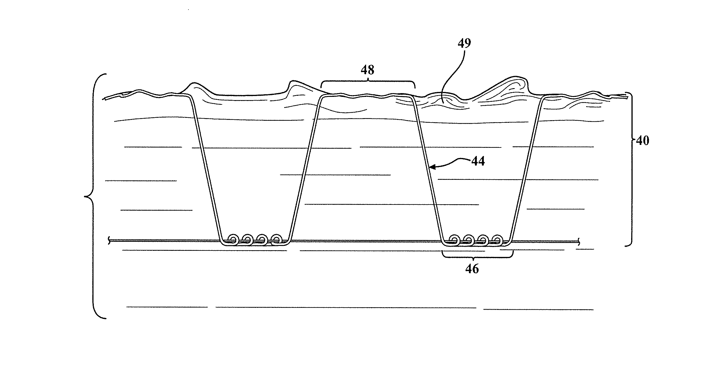
[0031]Referring now to FIG. 4, the present invention is shown. Again, the composite assembly 40 includes an elongated element 42 and a supplemental filament 44. However, this embodiment differs in that the supplemental filament 44 includes connected portions 46 that are connected to the elongated element 42 and detached portions 48 that are not connected to the elongated element 42 such that the detached portions 48 may extend away from the elongated element 42 when in the fluid environment. In the illustrated embodiment, the filament 44 is continuous such that the connected portions 46 and detached portions 48 are part of the same elongated element. In the illustrated embodiment, part of the detached portion 48 extends to upper boundary 49 of the fluid environment and floats thereon. This may be referred to as a floating portion, and is a part of the detached portion. A transition portion extends between the floating portion and the connected portion 46 by extending downwardly in t...


PUM


Abstract

An intrusion detection system includes a suspended optical fiber having a neutral buoyancy and an optical time-domain reflectometer connected to the suspended optical fiber at an origin location. The suspended optical fiber is connected to a mooring at a first end of the suspended optical fiber and further includes at least one terminal end. The optical time-domain reflectometer includes a light source operable to emit an optical pulse of light into the suspended optical fiber from the origin location toward the terminal end, and a processor operable to receive an optical return signal from the terminal end of the suspended optical fiber or from a deformation created by a disturbance to the suspended optical fiber and to determine a location and a type of the disturbance based on an analysis of at least a time to receive the optical return signal and a magnitude of the optical return signal.

Description

CROSS-REFERENCE TO RELATED APPLICATIONS[0001]This application claims priority to U.S. provisional patent application No. 62 / 237,770, filed Oct. 6, 2015. This application is also a continuation-in-part of U.S. patent application Ser. No. 15 / 268,769, filed Sep. 19, 2016, which is a continuation-in-part of application Ser. No. 14 / 319,232, filed Jun. 30, 2014, which claim the benefit of U.S. provisional application 61 / 957,421, filed Jul. 2, 2013. This application is also a continuation-in-part of U.S. patent application Ser. No. 14 / 319,232, which claims priority to U.S. provisional patent application No. 61 / 957,421, filed Jul. 2, 2013. The entire contents of each application are incorporated herein by reference.FIELD OF THE INVENTION[0002]This invention is directed to devices using fiber optical cable in an undersea environment as an intrusion detection system, and more specifically to methods for detecting disturbances over long distances using fiber optics suspended in the water colum...

Claims


Application Information

Patent Timeline
IPC IPC(8): G01D5/26G01V1/00
CPCG01V1/001G01D5/268G02B6/4427G02B6/506H02G1/10H02G9/12Y10T428/2933
Inventor YOUNG, RANDY
Owner PENN STATE RES FOUND
Why Eureka
Try Eureka