Method and System for Through-the-Wall Radar Imaging

Active Publication Date: 2017-01-26
MITSUBISHI ELECTRIC RES LAB INC
View PDF0 Cites 22 Cited by
  • Summary
  • Abstract
  • Description
  • Claims
  • Application Information

AI Technical Summary

Benefits of technology

The patent describes a method that uses a randomized Kaczmarz method to estimate a sparse scene and remove clutter caused by internal wall reflections. This method is efficient in using memory, especially when the antennas are located randomly. The method can be implemented on a handheld or mobile device with antennas and a display screen. The device transmits radar pulses and switches to receiving mode to acquire echoes reflected by objects. The device continues to send pulses from different locations while updating the current image based on the received echoes until a termination condition is reached. The changes in the locations improve the quality of the final image.

Problems solved by technology

However, depending on dielectric permittivity and permeability of the walls, the received signal is often corrupted with indirect secondary reflections due to the walls, which result in artifacts, such as ghosts, that clutter the radar image.

Method used


Image

  • Method and System for Through-the-Wall Radar Imaging
  • Method and System for Through-the-Wall Radar Imaging
  • Method and System for Through-the-Wall Radar Imaging

Examples


Embodiment Construction

[0026]System Setup

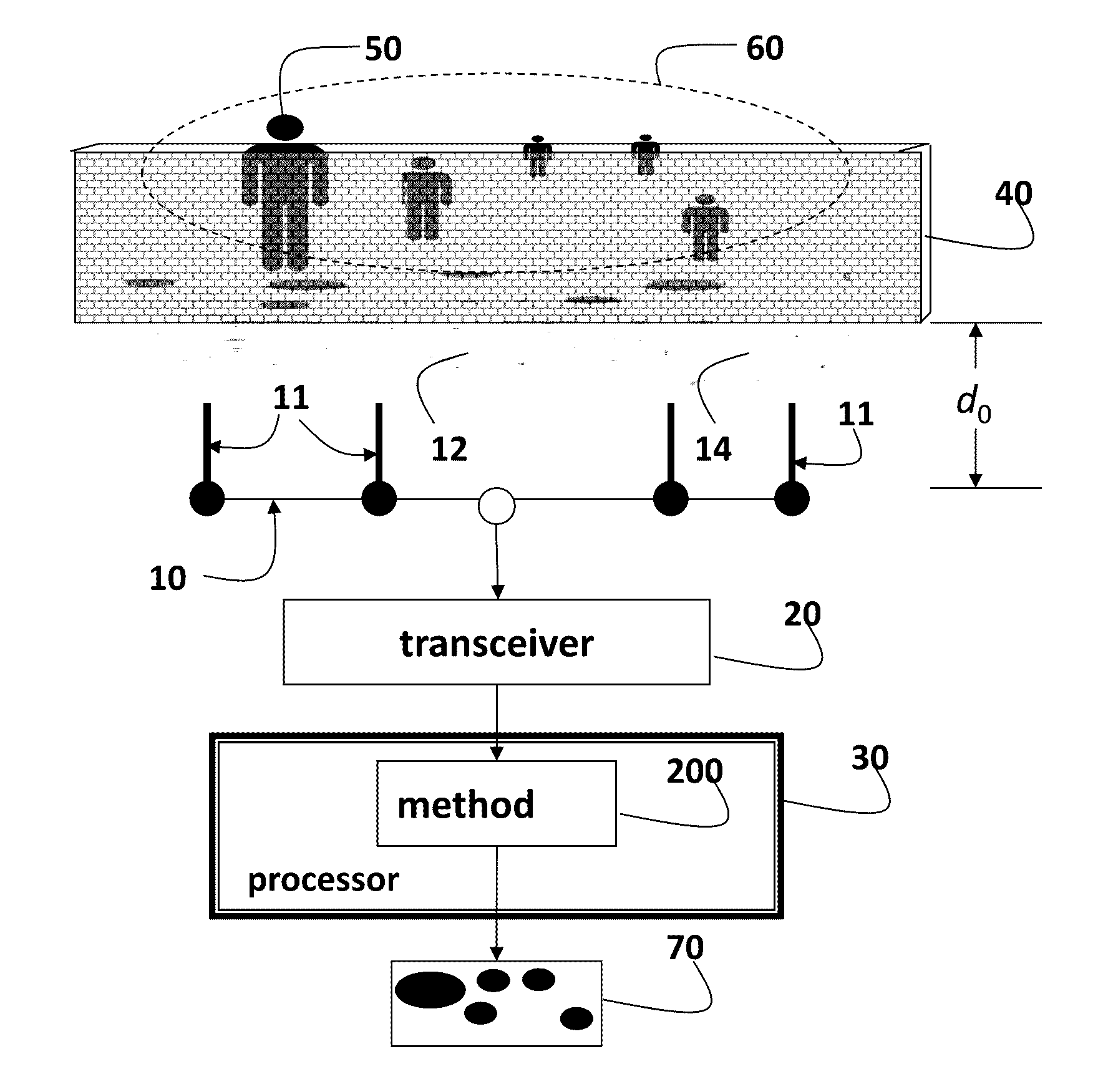
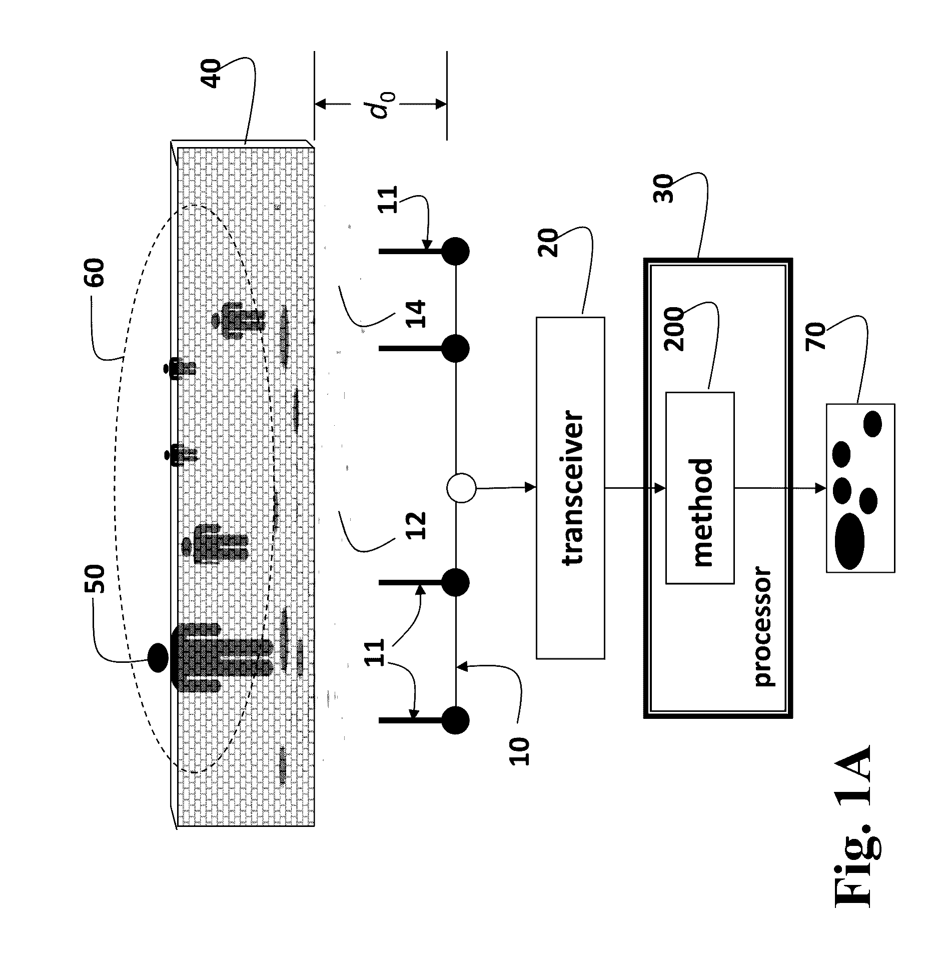
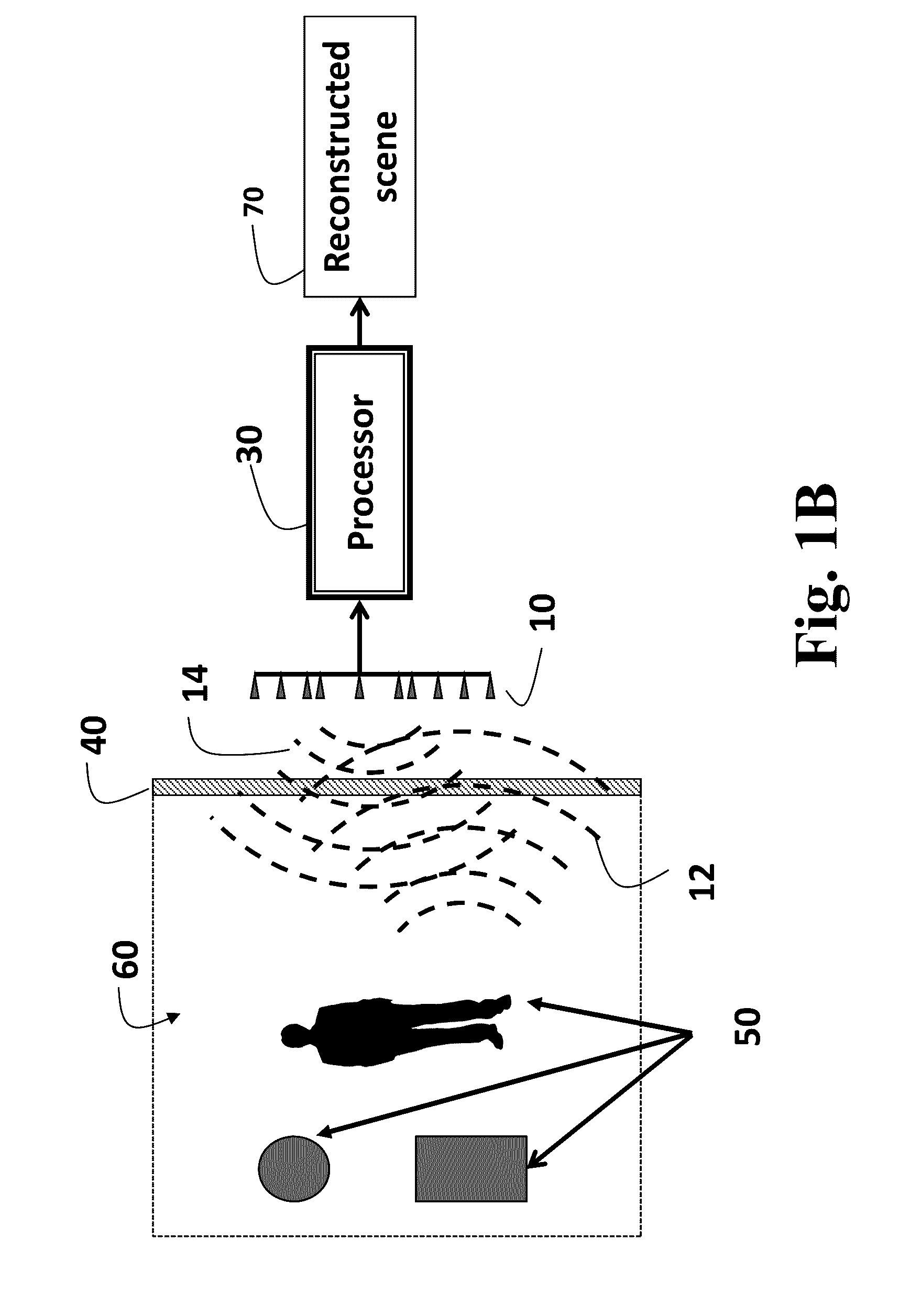
[0027]As shown in FIGS. 1A and 1B embodiments of our invention provide a system method and system for through-the-wall imaging (TWI) of objects 50 that do not require any prior knowledge of scene geometry. The method can reconstruct a scene 60 behind a wall 40.

[0028]The system includes an antenna array 10, transceiver 20, and processor 30. The transceiver can tranmit and receive radar pulses. The antenna comprises a set of one or more antenna elements 11. The antenna elements can either transmit or receive as controlled by the processor. The transceiver transmits one or more pulses 14 using one or more of the set of antenna elements 11 of the antenna array at a location in front of the wall. The transmitted pulse propagates through the wall 40 and are reflected by the possible objects 50 in a scene 60 behind the wall 40.

[0029]Reflected signals, (impulse responses or set of echoes) 12 corresponding to each pulse, are received by one or more antenna elements of the a...


PUM


Abstract

A method and system for generating an image of a scene behind a wall, wherein the scene is represented as a grid, by first transmitting a radar pulse through the wall using a transmitter and receiving a set of echoes corresponding to the radar pulse being reflected by the scene in a receiver at a known location. Based on the location, an imaging operator that relates the set of echoes to the grid is determined. Using the imaging operator, a sparse delay kernel that matches a response of a current image to a similar response in the set of echoes is determined. Then, the current image is updated, based on the set of echoes, the imaging operator, and the sparse delay kernel. The transmitting, the receiving, the determining, the obtaining, and the updating steps are repeated for different locations until a termination condition is reached.

Description

FIELD OF THE INVENTION[0001]This invention relates generally to radar imaging, and more particularly to through-the-wall radar (TWI) imaging.BACKGROUND OF THE INVENTION[0002]Through-the-wall-imaging (TWI) can detect objects in a scene behind a wall. In a typical application, a transmitting antenna array emits a radar pulse that propagates through the wall. The pulse is reflected by the objects and propagate back to a receiving antenna array as a set of echoes. The composition of the scene can then be visualized by generating a radar image that represents scene, including the number, locations and shape of the objects and reflectivities of the objects. However, depending on dielectric permittivity and permeability of the walls, the received signal is often corrupted with indirect secondary reflections due to the walls, which result in artifacts, such as ghosts, that clutter the radar image. Therefore, it is desired to reduction artifacts and significantly improve the quality and appl...

Claims


Application Information

Patent Timeline
IPC IPC(8): G01S13/89G01S13/02G01S7/06
CPCG01S13/89G01S13/02G01S7/06G01S13/888G01S2013/0245
Inventor MANSOUR, HASSANKAMILOV, ULUGBEK S.
Owner MITSUBISHI ELECTRIC RES LAB INC
Why Eureka
Try Eureka