Optical device sealing structure and optical deveice manufacturing method
a technology of sealing structure and optical device, which is applied in the direction of optics, thin material processing, instruments, etc., can solve the problems of time and cost, and the optical device may not be sealed in such a state, so as to reduce the cost of components, reduce the cost of members, and improve the sealing
- Summary
- Abstract
- Description
- Claims
- Application Information
AI Technical Summary
Benefits of technology
Problems solved by technology
Method used
Image
Examples
first embodiment
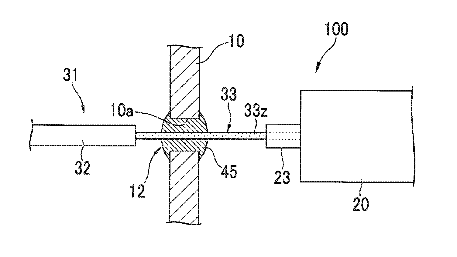
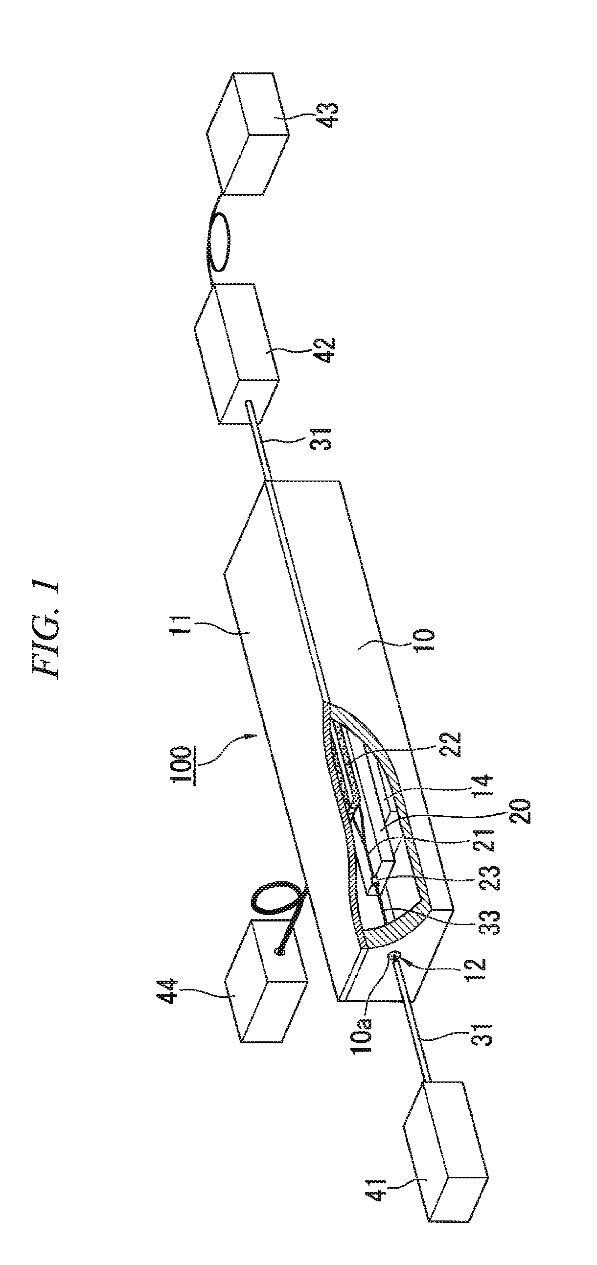
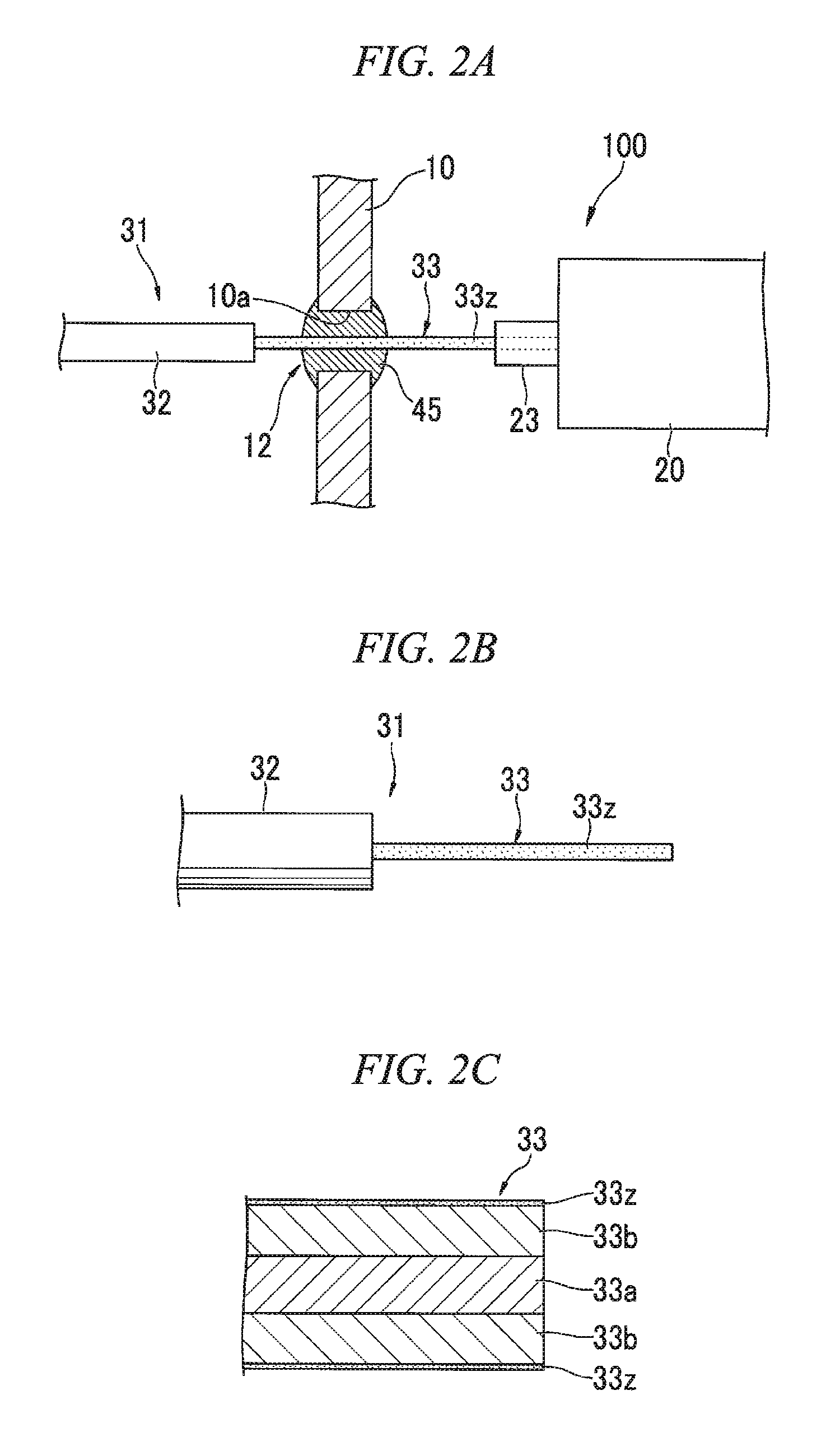
[0023]FIG. 1 is a diagram illustrating an optical waveguide package which is an embodiment of an optical device of the invention. FIGS. 2A to 2C are diagrams illustrating an optical waveguide package sealing structure.
[0024]An optical waveguide package (an optical device) 100 shown in FIG. 1 includes: a bottomed box-like case 10; an optical waveguide element (an optical element) 20 that is mounted into the case 10; a cover portion 11 that covers the opening end of the case 10 so as to be fixed thereto; and input and output optical fibers 31 that is connected to the optical waveguide element 20.
[0025]Furthermore, in FIG. 1, the case 10 and the cover portion 11 are partly notched so that the optical waveguide element 20 mounted therein is visible from the outside.
[0026]The optical waveguide element 20 is formed by installing a Mach-Zehnder optical waveguide 21 and an electrode 22 on a substrate which is formed of lithium niobate (LiNbO3; LN), and is fixed to a seat 14 inside the case ...
second embodiment
[0057]Next, a second embodiment will be described with reference to FIGS. 4A to 4C.
[0058]FIGS. 4A to 4C are diagrams illustrating an optical waveguide package manufacturing method according to the second embodiment.
[0059]The manufacturing method of the embodiment includes: forming the bare fiber portion 33 in which the bare fiber is exposed by partly removing the coating of the optical fiber 31; applying the Zn-containing solder 46 to the bare fiber portion 33; and inserting the optical fiber 31 into the through hole 10a of the case 10 and charging the Sn-containing soldering material 45 between the Zn-containing solder 46 on the bare fiber portion 33 and the inner wall of the through hole 10a.
[0060]First, as shown in FIG. 4A, the bare fiber portion 33 is formed in the optical fiber 31. The detailed procedure is the same as that of the above-described first embodiment.
[0061]Next, as shown in FIG. 4B, the Zn-containing solder 46 is partly applied to a predetermined position on the b...
third embodiment
[0072]Next, a third embodiment will be described by referring to FIGS. 5A and 5B.
[0073]FIGS. 5A and 5B are diagrams illustrating a method of manufacturing an optical waveguide package according to the third embodiment.
[0074]The manufacturing method of the embodiment includes: forming the bare fiber portion 33 in which the bare fiber is exposed by partly removing the coating of the optical fiber 31; and inserting the optical fiber 31 into the through hole 10a of the case 10 and charging the Zn-containing solder 46 between the bare fiber portion 33 and the inner wall of the through hole 10a.
[0075]First, as shown in FIG. 5A, the bare fiber portion 33 is formed in the optical fiber 31. The detailed procedure is the same as that of the above-described first embodiment.
[0076]Next, as shown in FIG. 5B, the bare fiber portion 33 of the optical fiber 31 is inserted into the through hole 10a of the case 10, and then the end portion of the bare fiber portion 33 is inserted into the connection...
PUM
 Abstract
Description
Claims
Application Information
 - R&D
- Intellectual Property
- Life Sciences
- Materials
- Tech Scout
- Unparalleled Data Quality
- Higher Quality Content
- 60% Fewer Hallucinations
Browse by: Latest US Patents, China's latest patents, Technical Efficacy Thesaurus, Application Domain, Technology Topic, Popular Technical Reports.
© 2025 PatSnap. All rights reserved.Legal|Privacy policy|Modern Slavery Act Transparency Statement|Sitemap|About US| Contact US: help@patsnap.com


