Axle welding alignment plates and method for using the same

a technology for axles and alignment plates, applied in the direction of soldering devices, manufacturing tools,auxillary welding devices, etc., can solve the problems of time-consuming and labor-intensive foregoing techniques on trailers or axles with welded spiders, distortion and non-alignment of the races with respect to one another, etc., to achieve time and labor-saving, enhance the use of devices and methods

Inactive Publication Date: 2017-02-02
FERRARI WILLIAM J
View PDF11 Cites 20 Cited by
  • Summary
  • Abstract
  • Description
  • Claims
  • Application Information

AI Technical Summary

Benefits of technology

[0006]It is an object of this invention to provide solutions suitable for axle repairs where more than the outer bearing surface has been damaged. It is another object to enhance the devices and methods used for repairing trailer axles and some drive axles with welded brake spiders.
[0007]In this invention, an alignment plate or platform is provided which has means for adjusting its location with respect to the axis of the vehicle axle. The alignment plates assist with setting a proper positive camber and toe. The alignment means include clamping a first alignment plate to a first jig element and affixing a second alignment plate at an opposed end of the welding set up with both alignment plates being sequentially numbered or lettered and rotatable until a proper alignment is achieved before welding commences.
[0008]In addition, gauges aid in the adjustment for locating the alignment platform with respect to the axle, trailer, drive or both types. With the alignment platform properly located, a replacement part is properly held in place for welding. It represents a time and labor savings when effecting a welding repair to a vehicular (truck or automotive) axle. Prior welding alignment means included adding a crude locator stick (item S in FIG. 1) on one of the repair ends, moving back and forth about the whole length of a set up axle for repair (could be six to eight feet in length) and then sometimes visually estimating an alignment with that locator stick before the welding repair commences.

Problems solved by technology

The foregoing technique has been more time consuming on trailers or axles with welded spiders.
Even when manufactured with the races in place on a good axle, there is always distortion and non-alignment of the races with respect to one another caused by the process of welding the struts to the races.
This necessitates having to force the jig during placement and removal.

Method used


Image

  • Axle welding alignment plates and method for using the same
  • Axle welding alignment plates and method for using the same
  • Axle welding alignment plates and method for using the same

Examples


Embodiment Construction

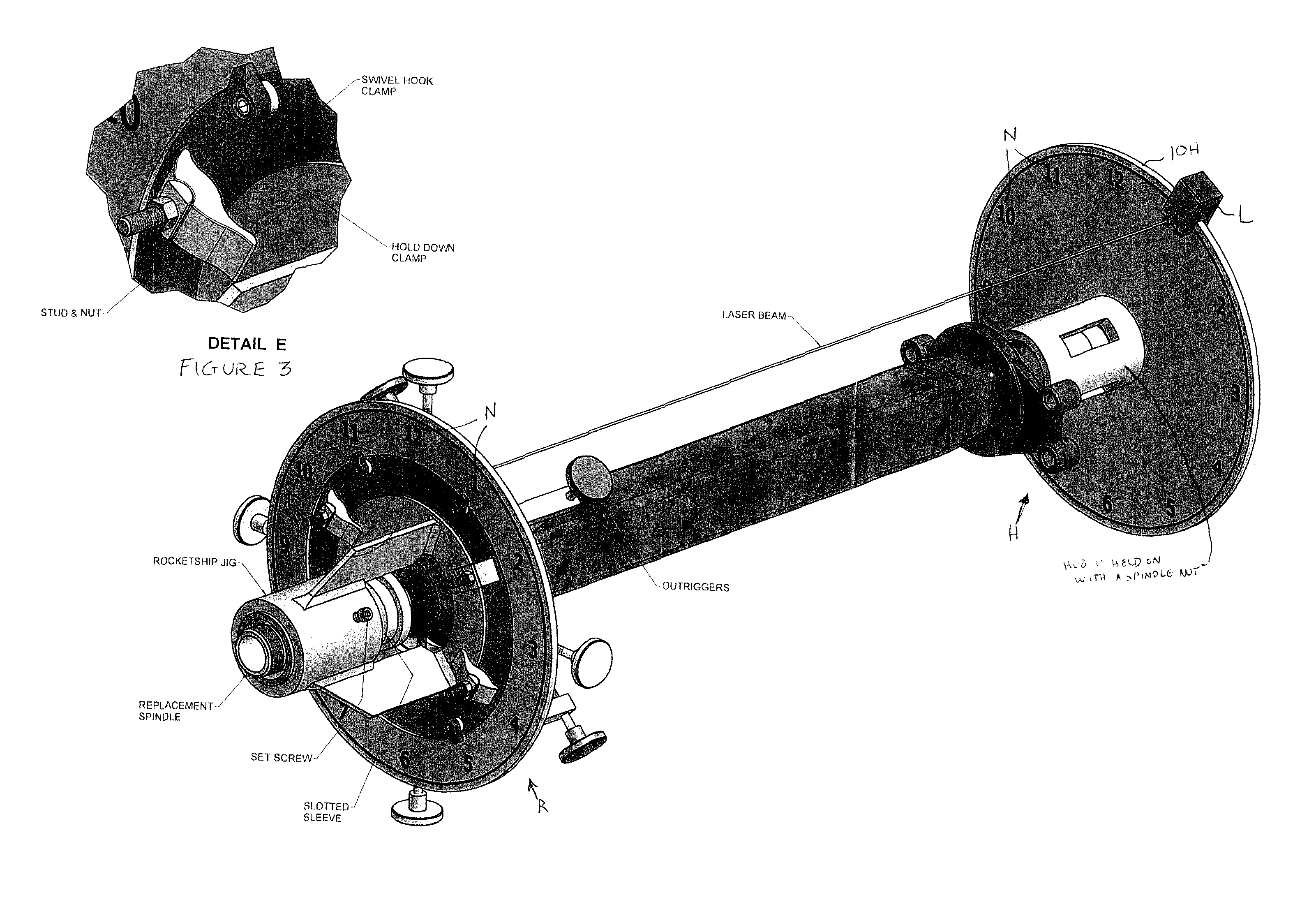
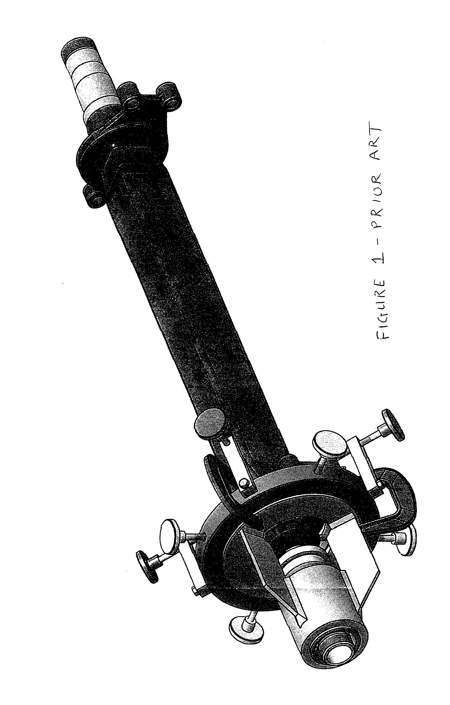
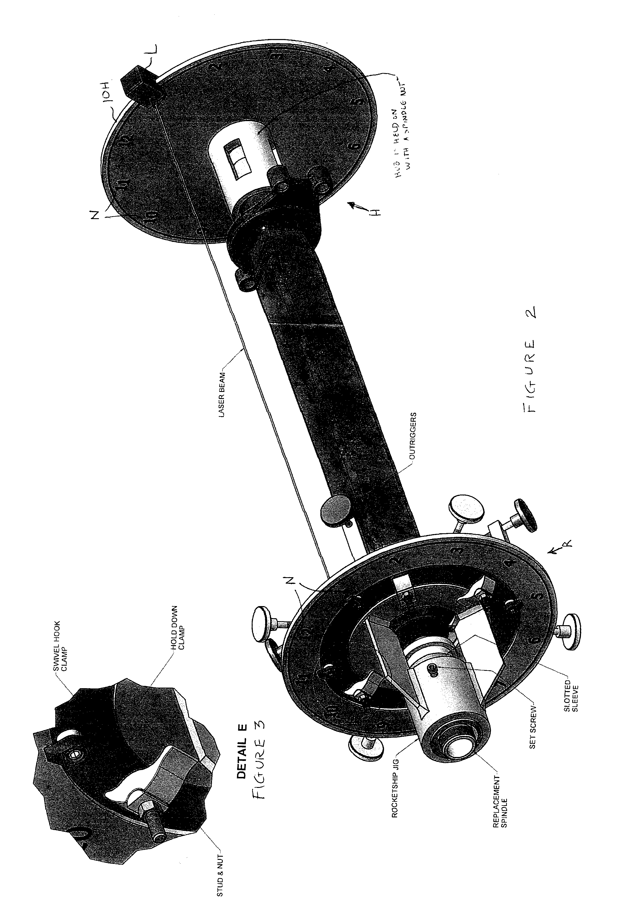
[0012]FIGS. 1 through 3 illustrate by comparison one old (FIG. 1) versus new (FIGS. 2 and 3) trailer axle jig arrangement, the latter two employing one preferred embodiment of this invention. As is evident in FIG. 1, trailer axle jigs prior to this invention had no outside clamping mechanisms (which is better seen in the enlarged focus view of FIG. 3). The swivel clamps of this invention, by contrast, hold the jig with its recessed plate for better alignment with gauges that include laser components and more accurate, more ideal proper positioning brackets. The latter lets an operator align the two ends in a weld repair situation, i.e., the replacement spindle end R versus the opposed hub and spindle nut end H. The two alignment plates, 10R and 10H, include numerical indicators N so as to appear like the face of a clock (hence the time notations at 1 o'clock through 12 o'clock). Alternately, the faces of one or both alignment plates may be sequentially lettered (not shown), from “A”...


PUM

PropertyMeasurementUnit
lengthaaaaaaaaaa
areaaaaaaaaaaa
sizeaaaaaaaaaa

Abstract

A set of alignment plates is provided for adjusting the relative location of the two ends of a vehicle axle with respect to one another prior to the commencement of a welding repair thereon. A first alignment plate clamps to a first jig element and a second alignment plate affixes to an axle component at the opposed (hub) end, both alignment plates being sequentially numbered or lettered and rotatable until proper alignment is achieved.

Description

CROSS-REFERENCE TO RELATED APPLICATION[0001]This is a perfection of provisional application Ser. No. 62 / 196,168 filed on Jul. 23, 2015, the disclosure of which is fully incorporated by reference herein.TECHNICAL FIELD[0002]This invention relates to vehicular axle repair methods and apparatus improvements relating to the same. They are intended as further advancements from my original disclosures in U.S. Pat. Nos. 4,792,080 and 5,125,146. These improvements are applicable to trailer axle repairs and certain drive axles with welded on brake spiders. They can be used to repair an axle in a welding repair shop OR at the actual axle failure site.BACKGROUND OF THE INVENTION[0003]It is known to make a welded jig to temporarily hold a replacement terminal portion in place with respect to the remainder of an axle, until the terminal portion has been partially welded to the remainder of the axle at the joint between them. That welded jig is composed of two inner adapters (instead of bearing r...

Claims


Application Information

Patent Timeline
Patent Type & Authority Applications(United States)
IPC IPC(8): B23P6/04B23K37/053
CPCB23P6/04B23K37/0538B23K37/0533B23K37/0443B23K37/053
Inventor FERRARI, WILLIAM J.
Owner FERRARI WILLIAM J
Why Eureka
Try Eureka