
Speed enhancement for HVAC mode kinematics

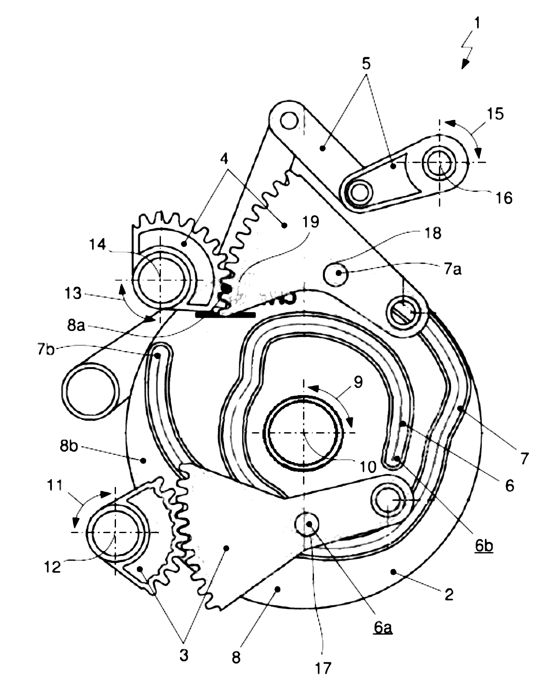
a technology of hvac mode and kinematics, applied in the direction of vehicle cleaning, heating types, lighting and heating apparatus, etc., can solve the problems of time delay between, added technical complexity and cost, and the “dashboard damper open” setting may not necessarily be desired, so as to avoid undesired passage, clear visibility through the windshield

Inactive Publication Date: 2017-02-02
HANON SYST
View PDF3 Cites 5 Cited by
  • Summary
  • Abstract
  • Description
  • Claims
  • Application Information

AI Technical Summary

Benefits of technology

The invention is a system and method for controlling the air conditioning system of a vehicle to prevent fogging of the windshield while still providing comfortable temperatures for the passengers. The main technical effect of the system is that it reduces the time and prevents the system from hitting unexpected air distribution settings, which can cause fogging of the windshield. This ensures that the vehicle's passengers are always comfortable and can see clearly through the windshield.

Problems solved by technology

With an electrical transmission of the air distribution setting via an electrical connection to an electrical servo motor for adjusting the cam disk, a time delay occurs between the selection of the desired setting via the control unit and the actual adjustment of the air conditioning unit due to the rotating speed of the servo motor, based on its technical specifications.
However, additional servo motors result in added technical complexity and costs, in terms of both the air conditioning system and the operating unit.
However, the “dashboard damper open” setting may not necessarily be desired.
Moreover, when sweeping through the entire angle range of the cam disk, the system passes through air distribution settings such as “dashboard damper open” and footwell damper open”, which may be unexpected, undesirable or even unpleasant to the operator or the driver of the motor vehicle.
However, the arrangement of the settings is not consistent with that of a traditional control element, for example in the form of a rotary knob, causing irritation for the operator or driver of the motor vehicle.

Method used


Image

  • Speed enhancement for HVAC mode kinematics
  • Speed enhancement for HVAC mode kinematics
  • Speed enhancement for HVAC mode kinematics

Examples


Embodiment Construction

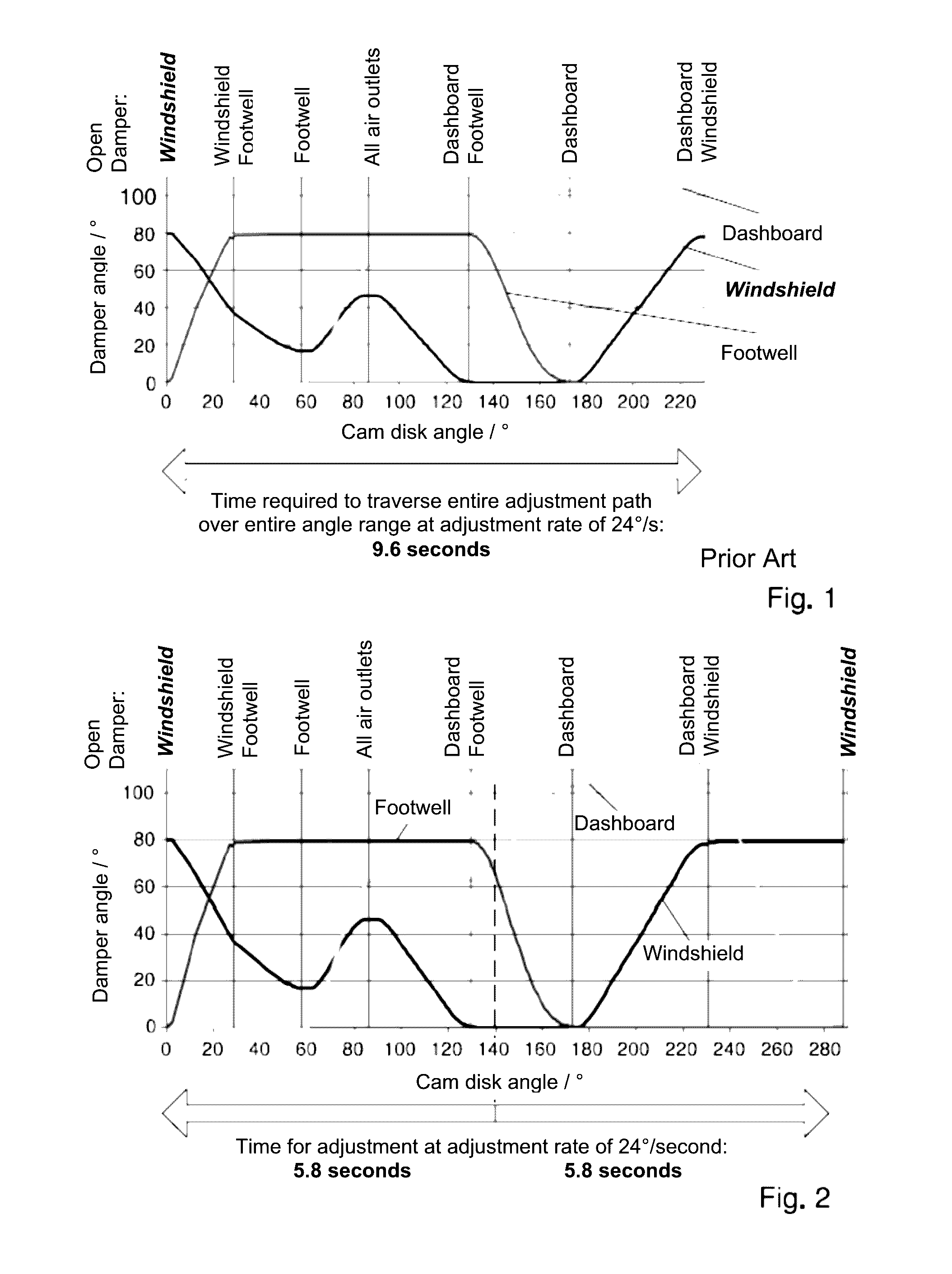
[0067]FIG. 2 shows a graph illustrating the sequence of positions of the dampers and the air distribution settings based on the damper angle, as a function of the position of a cam disk of the air distribution system that has maximum adjustment times to reach the “windshield damper open” setting.

[0068]As in FIG. 1, the angles of each of the dampers of the air outlets toward the windshield, in the dashboard and into the footwell are plotted using individual characteristic curves as a function of the angle of the cam disk being adjusted.

[0069]As compared with the air distribution setting according to FIG. 1, the cam disk is rotatable within an angle range of 0° to 288°. The expansion of the angle range from 230° to 288° enables the creation of a second “windshield damper open” setting. The flow path to the air outlets toward the windshield is therefore open at a cam disk angle of around 0°, at a cam disk angle of around 230° in a blended setting with the flow path toward the air outle...


PUM


Abstract

A system and method for air distribution in an air conditioning system of a motor vehicle, the system including flow paths with air outlets toward the windshield, in the dashboard, and toward the footwell, along with a central gear mechanism having an adjustment element and damper controls for air dampers, for the purpose of opening and closing the air outlets. The adjustment element is arranged to be steplessly movable between a first end position and a second end position. With the system, in particular by moving the adjustment element, the settings “windshield damper open”, “footwell damper open” and “dashboard damper open” may be selected. The central gear mechanism having the adjustment element and the damper controls is configured such that the “windshield damper open” setting may be selected at either of the end positions of the adjustment element.

Description

CROSS-REFERENCE TO RELATED PATENT APPLICATION[0001]This patent application claims priority to German Patent Application No. DE 102015112378.9 filed on Jul. 29, 2015, the disclosure of which is incorporated herein by reference in its entirety.FIELD OF THE INVENTION[0002]The invention relates to a system and method for air distribution in an air conditioning system of a motor vehicle. The system comprises flow paths with air outlets toward the windshield, in the dashboard and toward the footwell, and a central gear mechanism having an adjustment element and damper controls for air dampers designed for opening and closing the air outlets. The adjustment element can be moved steplessly between two end positions, allowing the system to be adjusted to the air distribution settings “windshield damper open”, “footwell damper open” and “dashboard damper open”.BACKGROUND OF THE INVENTION[0003]Conditioning the air within the passenger compartment of a motor vehicle, in addition to providing a ...

Claims


Application Information

Patent Timeline
Patent Type & Authority Applications(United States)
IPC IPC(8): B60H1/00B60S1/02
CPCB60H1/00842B60H2001/00707B60H1/00678B60S1/023B60H1/0065B60H1/00857B60H1/34B60H2001/3478F24F13/1426
Inventor WIESMANN, RALPHNOWAK, MARTIN PAULFERREIRA, ANTONIO ALBERTO MARQUESHANDWERK, DETLEF
Owner HANON SYST
Learn More