Charging station having a charging cable

a charging station and charging cable technology, applied in the direction of power cables, conductors, electric vehicles, etc., can solve the problems of prolonging the charging duration, and affecting the charging operation

Active Publication Date: 2017-02-02
DR ING H C F PORSCHE AG
View PDF3 Cites 33 Cited by
  • Summary
  • Abstract
  • Description
  • Claims
  • Application Information

AI Technical Summary

Benefits of technology

[0014]It is particularly advantageous if the charging station, the part fluid circuit and / or the part fluid duct have means for controlling the temperature of the fluid. The fluid can thus be preconditioned itself in advance to a suitable temperature for the optimum temperature control of the charging cable and the contact elements.
[0015]It is advantageous here if the means for controlling the temperature have a heating means for heating the fluid and / or cooling means for cooling the fluid. As a result, the fluid can be heated or cooled, with the result that the desired temperature of the charging cable and / or the contact elements can be achieved.
[0016]It is also advantageous if the fluid is air which can be sucked in, in particular, from the exterior space of the charging station, or is another gas or gas mixture or a liquid which can be sucked in from a reservoir.
[0017]It is particularly advantageous if, in addition to the electrically connecting lines, the charging cable also has the part fluid ducts, the electrically connecting lines being in thermal connection with the part fluid ducts. Temperature control of the electrically connecting lines can thus take place over the length of the charging cable, with the result that its temperature can likewise be stabilized over its length.

Problems solved by technology

Since the electric energy stores can heat up to a pronounced extent in charging operations of this type, which might be detrimental to the power output and the service life of the energy store, cooling options have been disclosed in the prior art, by means of which the electric energy store can be cooled.
It has been shown, however, that the quality of the electric contact between the vehicle-side plug-in apparatus and the charging station-side plug-in apparatus is variable, in particular, even in the case of changing exterior conditions and even during the charging operation, and said electric contact can become worse during the charging operation, with the result that the plug-in apparatus can be heated to an undesirably pronounced extent and the charging operation can be impaired disadvantageously as a result, which is either manifested in a lower charging capacity after the charging or which can lead to lengthening of the charging duration.

Method used


Image

  • Charging station having a charging cable
  • Charging station having a charging cable
  • Charging station having a charging cable

Examples


Embodiment Construction

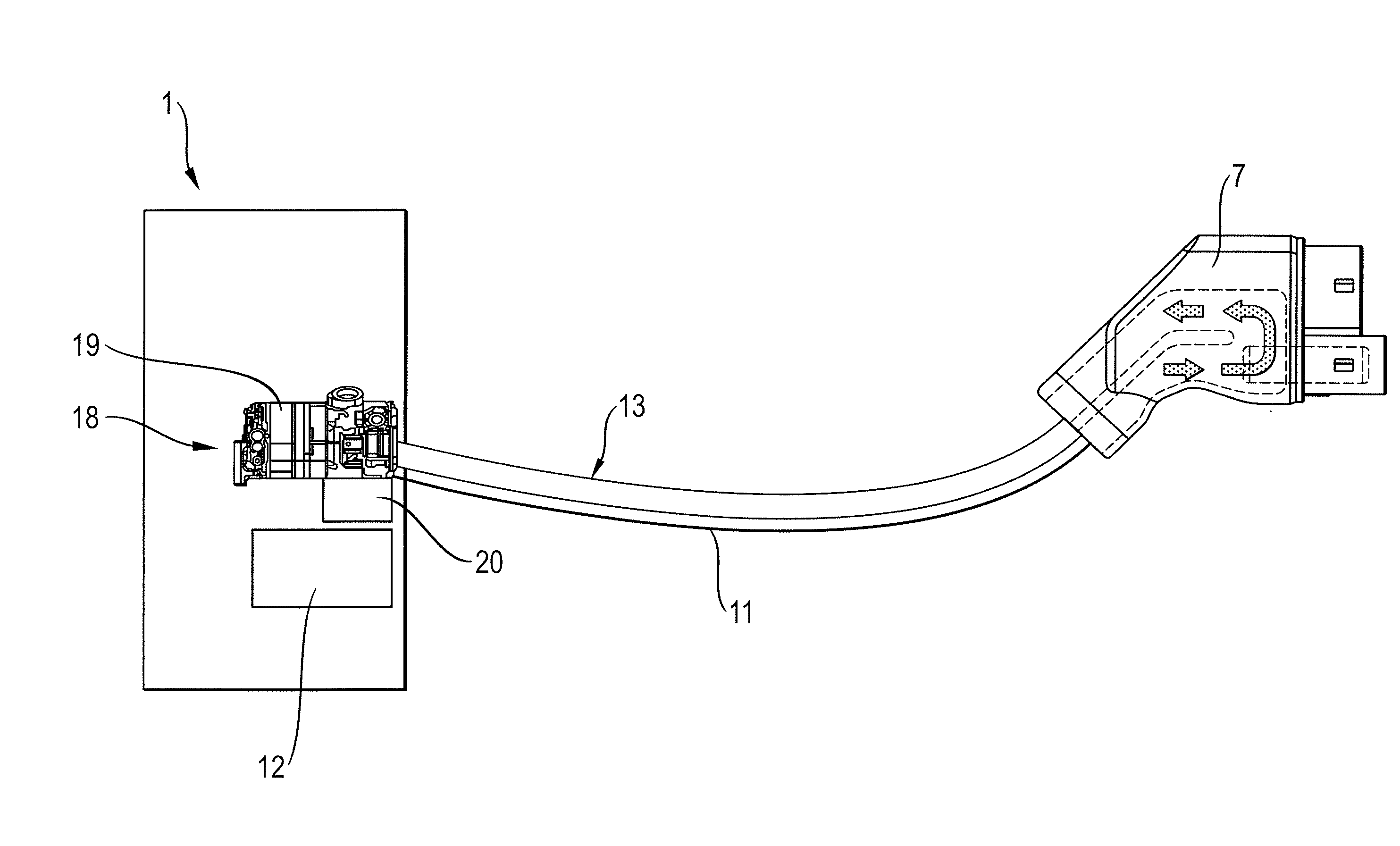
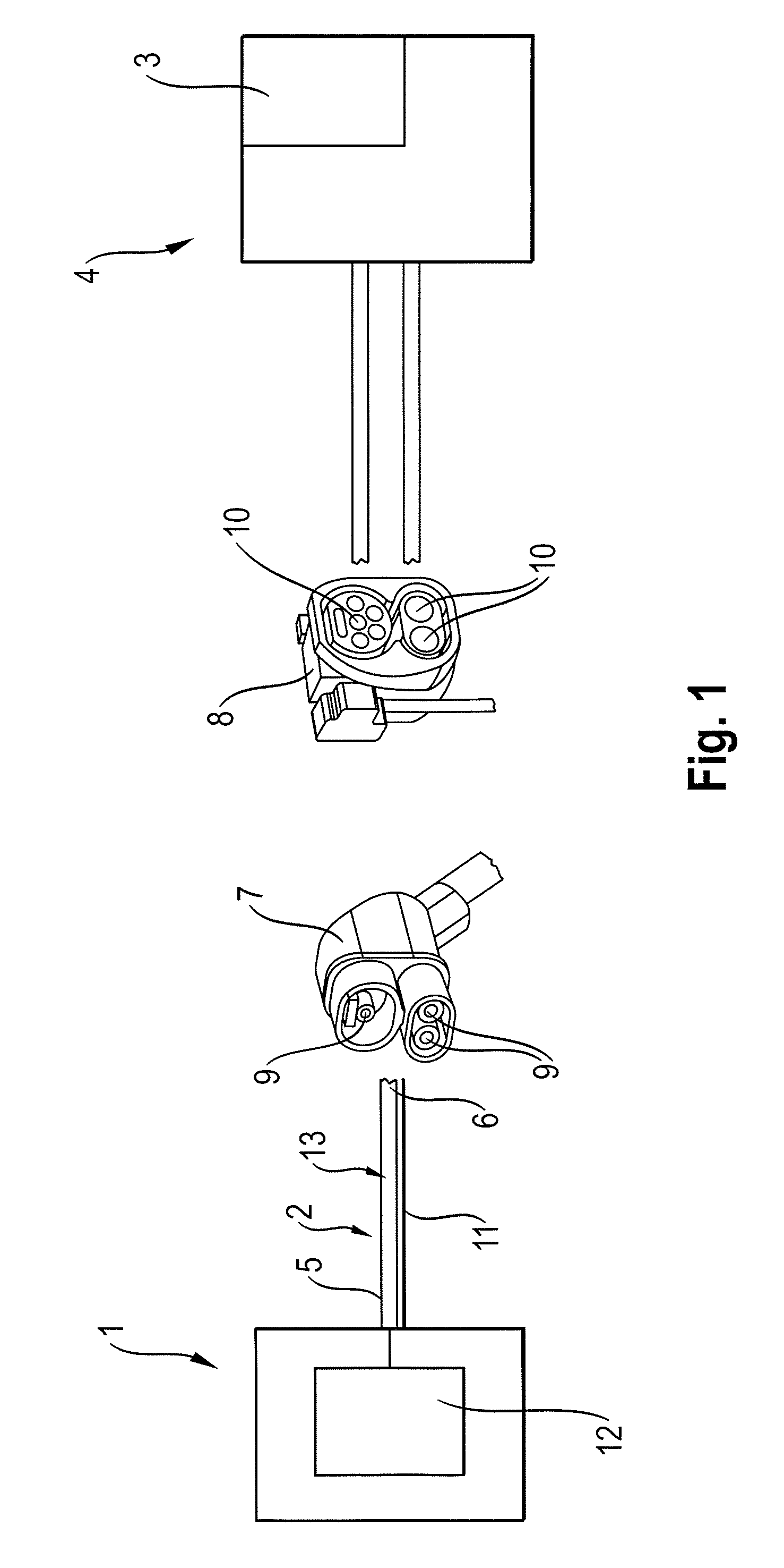
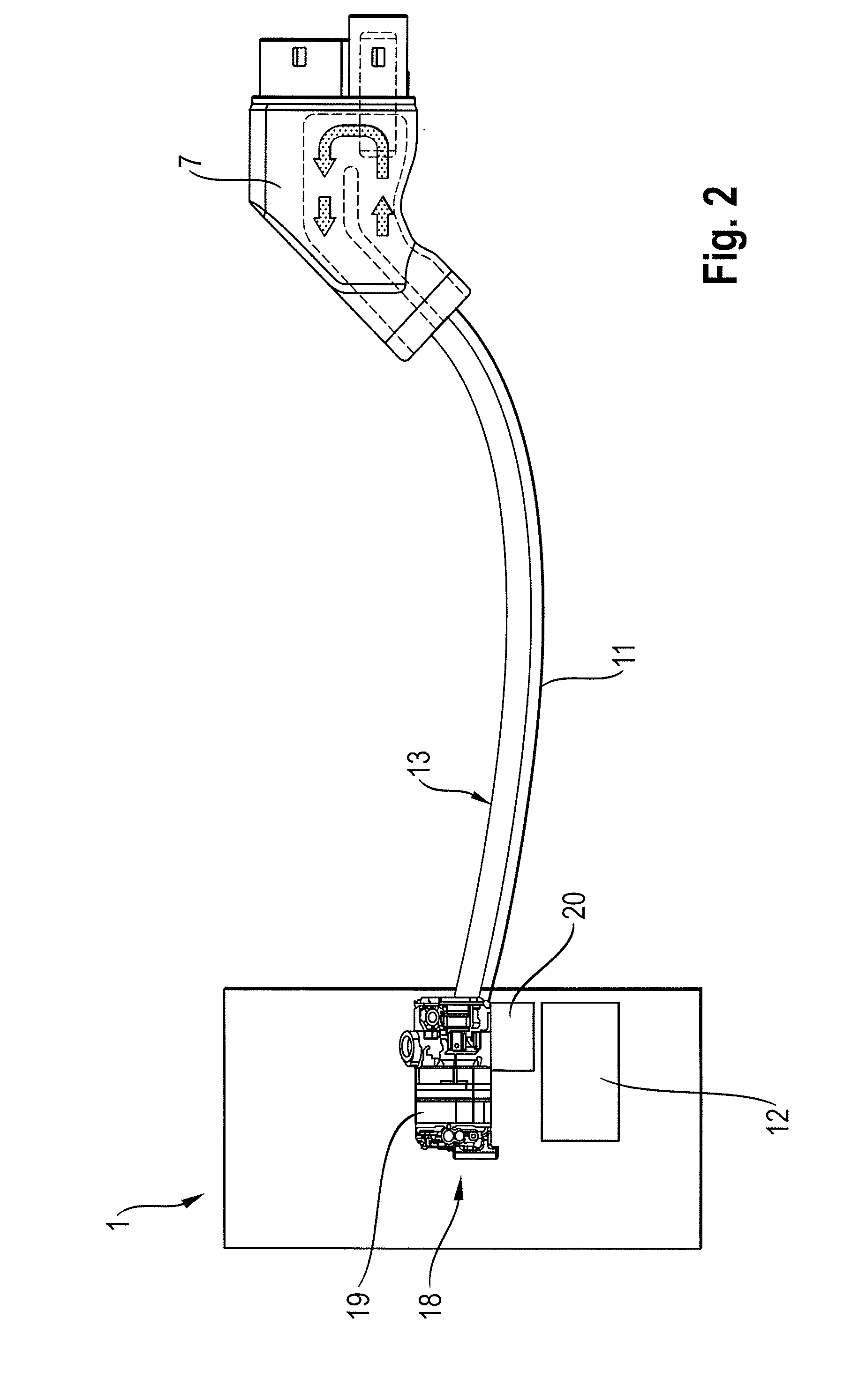
[0023]FIGS. 1 to 4 show different views of one exemplary embodiment with a charging station 1 having a charging cable 2 for charging an electric energy store 3. The electric energy store 3 is part of an apparatus 4. The charging cable 2 is connected to the charging station 1 at a proximal end 5. The charging cable 2 is also configured with a first plug-in apparatus 7 at a distal end 6, for connecting to a second plug-in apparatus 8 of the apparatus 4 which is to be charged and contains an electric energy store 3. The first plug-in apparatus is advantageously configured as a plug, such as a male part of a plug, the second plug-in apparatus being configured as a female part of a plug. The first plug-in apparatus can likewise also be configured as a plug, such as a female part of a plug, it being possible for the second plug-in apparatus to be configured as a male part of a plug.

[0024]The first plug-in apparatus 7 has first electric contact elements 9 for electric connection to second ...


PUM

PropertyMeasurementUnit
temperatureaaaaaaaaaa
temperaturesaaaaaaaaaa

Abstract

A charging station having a charging cable for charging an electric energy store, the charging cable being connected to the charging station at a proximal end and having a first plug-in apparatus at a distal end for connecting to a second plug-in apparatus of an apparatus to be charged which contains an electric energy store, the first plug-in apparatus having first electric contact elements for electric connection to second electric contact elements of the second plug-in apparatus, the charging cable having electrically connecting lines for electric connection of the first contact elements to a voltage source of the charging station, the charging cable having a fluid duct for guiding a fluid from the charging station toward the first plug-in apparatus and from the first plug-in apparatus back to the charging station again.

Description

CROSS-REFERENCE TO RELATED APPLICATIONS[0001]This application claims priority to German Patent Application No. 10 2015 112 347.9, filed Jul. 29, 2015, which is incorporated by reference herein in its entirety.FIELD OF THE INVENTION[0002]The invention relates to a charging station having a charging cable, in particular for charging an electric energy store of a motor vehicle.BACKGROUND OF THE INVENTION[0003]Motor vehicles having an electric motor as drive motor have to be charged at charging stations, in order that they can store the necessary energy for a journey of the motor vehicle. To this end, the motor vehicle has an electric energy store and a plug-in apparatus which can be connected by means of a charging cable with a correspondingly compatible plug-in apparatus to a charging station, in order for it to be possible to charge the electric energy store. Here, the electric energy stores are often supplied with a high voltage charge current.[0004]Since the electric energy stores ...

Claims


Application Information

Patent Timeline
Patent Type & Authority Applications(United States)
IPC IPC(8): B60L11/18H01B9/00H01B7/42
CPCB60L11/1818B60L11/1825B60L2230/12H01B9/006H01B7/423H02J7/0027B60L53/16B60L53/18B60L53/302B60L53/31Y02T10/70Y02T10/7072Y02T90/12Y02T90/14H02J7/00
Inventor NAGEL, THOMASREMISCH, DIRK
Owner DR ING H C F PORSCHE AG
Why Eureka
Try Eureka