Optical lens, lens array, and lighting apparatus

Inactive Publication Date: 2017-02-02
PANASONIC INTELLECTUAL PROPERTY MANAGEMENT CO LTD
View PDF6 Cites 9 Cited by
  • Summary
  • Abstract
  • Description
  • Claims
  • Application Information

AI Technical Summary

Benefits of technology

Technical effects: The present disclosure provides an optical lens that reduces light emitted in an undesired direction, such as rearward light emission through the optical lens.

Problems solved by technology

If a lighting apparatus emits light rearward of the lighting apparatus, this causes glare, for example.

Method used


Image

  • Optical lens, lens array, and lighting apparatus
  • Optical lens, lens array, and lighting apparatus
  • Optical lens, lens array, and lighting apparatus

Examples


embodiment 1

[0025]The following specifically describes embodiments, with reference to the drawings. The embodiments described below each show a general or specific example. The numerical values, shapes, materials, elements, the arrangement and connection of the elements, and others indicated in the following embodiments are mere examples, and thus are not intended to limit the present disclosure. Therefore, among the elements in the following embodiments, elements not recited in any of the independent claims defining the most generic part of the inventive concept are described as arbitrary elements. In addition, the drawings are schematic diagrams, and do not necessarily provide strictly accurate illustration.

[Entire Configuration]

[0026]The following describes alighting apparatus according to Embodiment 1.

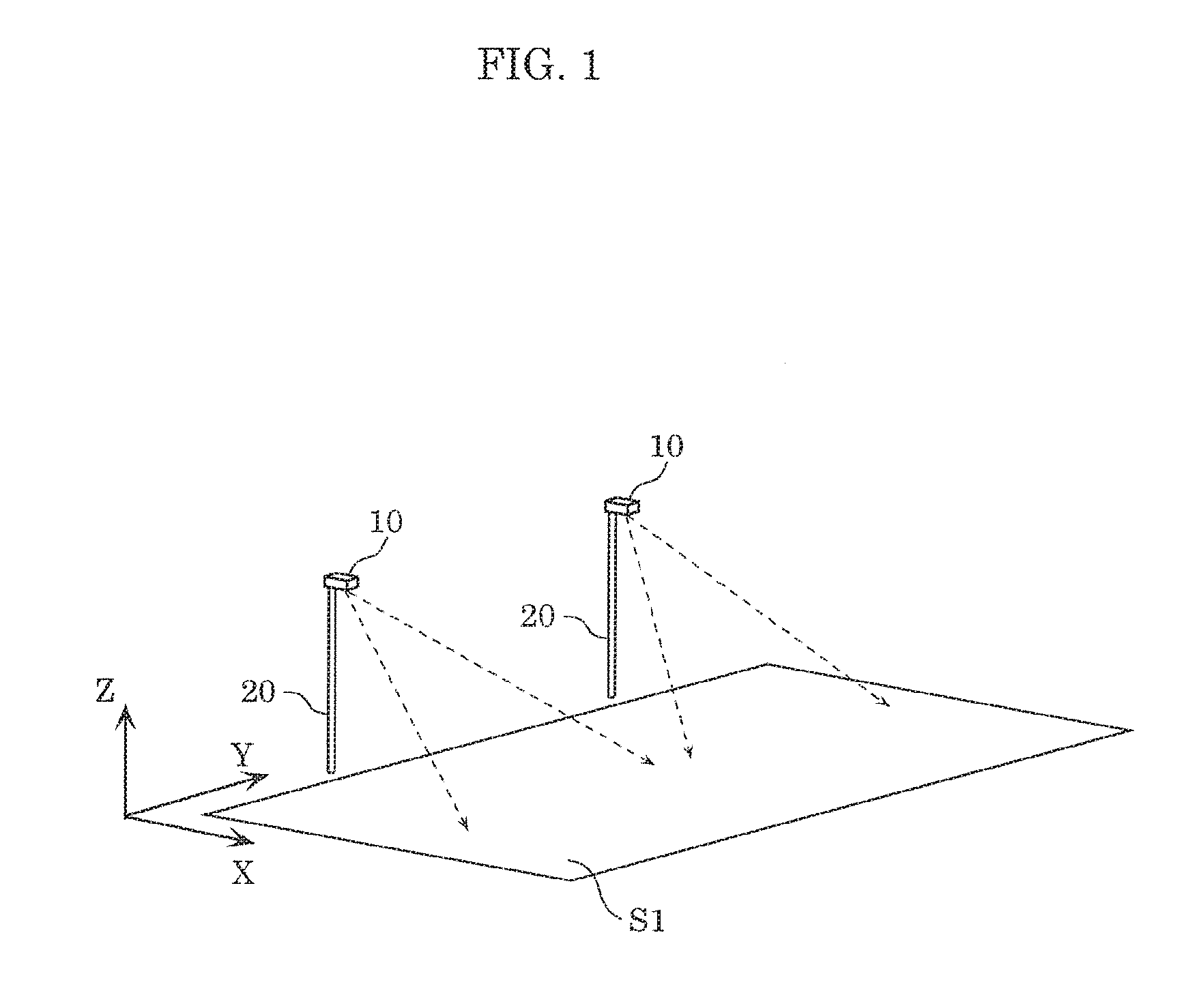
[0027]FIG. 1 is a perspective view illustrating schematic structures of the lighting apparatuses according to Embodiment 1.

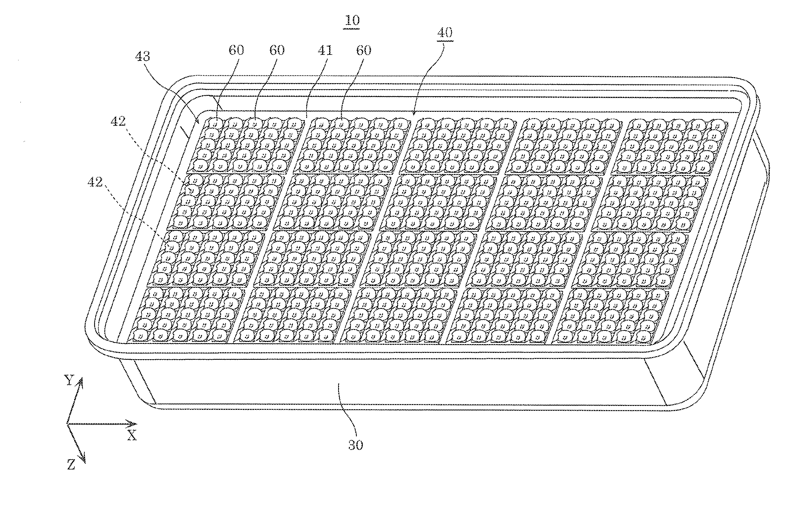
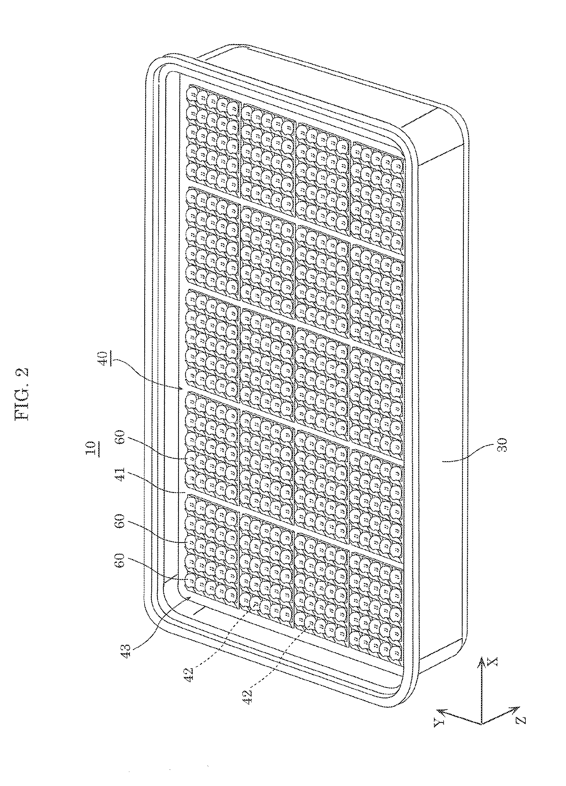
[0028]As illustrated in FIG. 1, lighting apparatus 10 is supported at...

embodiment 2

[0085]Embodiment 1 has described an example in which portion 625 of the joint between third lens surface 623 and second lens surface 622 is at or adjacent to an intersection between tilted line L5 and second lens surface 622. Embodiment 2 describes a case where a portion of a joint between a third lens surface and a second lens surface is at a different position from that of Embodiment 1.

[0086]Note that in the following description, the same portion as that in Embodiment 1 is given the same numeral, and a description thereof may be omitted.

[0087]FIG. 9 is a cross-sectional view illustrating a schematic structure of optical lens 60A according to Embodiment 2, and corresponds to FIG. 6.

[0088]As illustrated in FIG. 9, in optical lens 60A, portion 625a of a joint between second lens surface 622a and. third lens surface 623a is at or adjacent to an intersection between second lens surface 622a and normal line L6 to substrate 41, which is passing through a vertex of first lens surface 621...

embodiment 3

[0092]Embodiment 2 has described an example in which portion 625a of the joint between third lens surface 623a and second lens surface 622a is at or adjacent to an intersection between second lens surface 622a and normal line L6 to substrate 41, which is passing through the vertex of first lens surface 621. Embodiment 3 describes the case where a portion of a joint between a third lens surface and a second lens surface is at a different position from those of Embodiments 1 and 2.

[0093]Note that in the following description, the same portion as that of Embodiments 1 and 2 is given the same numeral, and the description thereof may be omitted.

[0094]FIG. 10 is a cross-sectional view illustrating a schematic structure of optical lens 60B according to Embodiment 3, and corresponds to FIGS. 6 and 9.

[0095]As illustrated in FIG. 10, in optical lens 60B, portion 625b of a joint between second lens surface 622b and third lens surface 623b is at or adjacent to an intersection between optical ax...


PUM


Abstract

An optical lens includes: a first lens surface which defines a space for housing a light emitting diode (LED) light source; a second lens surface formed in a convex shape; and a third lens surface formed continuously from a rear edge portion of the second lens surface, which is on a side opposite an illumination target side. The first lens surface includes a first light-entering surface through which a portion of light from the LED light source enters, and a second light-entering surface through which another portion of the light enters. The third lens surface totally reflects, to a substrate, at least a portion of the light. An angle between the third lens surface and a principal surface of the substrate on a virtual plane which includes an optical axis is smaller than an angle between the second light-entering surface and the principal surface on the virtual plane.

Description

CROSS REFERENCE TO RELATED APPLICATION[0001]This application claims the benefit of priority of Japanese Patent Application Number 2015-149054 filed on Jul. 28, 2015, the entire content of which is hereby incorporated by reference.BACKGROUND[0002]1. Technical Field[0003]The present disclosure relates to an optical lens, a lens array, and a lighting apparatus.[0004]2. Description of the Related Art[0005]For example, lighting apparatuses disposed outside, such as road lights, street lights, tunnel lights, and parking lot lights, are often installed on lighting poles, for instance. The place where a lighting pole is installed is at a location where the pole does not block the paths of persons, vehicles, and so on. For example, if a lighting pole is installed on the roadside, an illumination target that is to be illuminated by a lighting apparatus is at a location shifted forward (toward the road) from the place where the lighting apparatus is installed. If a lighting apparatus emits lig...

Claims


Application Information

Patent Timeline
IPC IPC(8): F21V5/00F21V5/04F21V7/00F21K9/64F21V13/04
CPCF21V5/007F21K9/64F21V13/04F21Y2105/10F21V5/04F21Y2115/10F21W2131/103F21V7/0091F21S2/00F21S8/086F21V5/08F21Y2105/16
Inventor HIRAI, JUNMURAKAMI, TADASHI
Owner PANASONIC INTELLECTUAL PROPERTY MANAGEMENT CO LTD
Why Eureka
Try Eureka