Light emitting device assembly and headlamp including the same

Active Publication Date: 2012-11-22
SAMSUNG ELECTRONICS CO LTD
View PDF7 Cites 18 Cited by
  • Summary
  • Abstract
  • Description
  • Claims
  • Application Information

AI Technical Summary

Benefits of technology

[0012]According to an aspect of the present invention, there is provided a light emitting device (LED) assembly and a

Problems solved by technology

However, an LED headlamp used for a vehicle is in a first stage of development, and is being developed slowly.
In a structure excluding the cutoff shield, a light emitted from a light source may disper

Method used


Image

  • Light emitting device assembly and headlamp including the same
  • Light emitting device assembly and headlamp including the same
  • Light emitting device assembly and headlamp including the same

Examples


Example

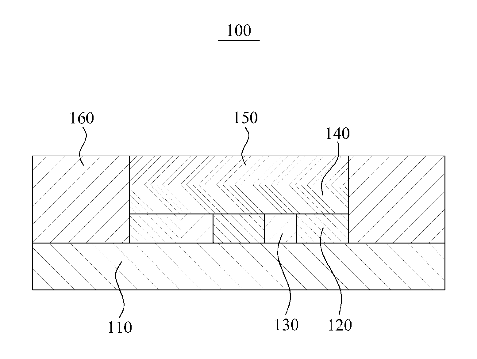
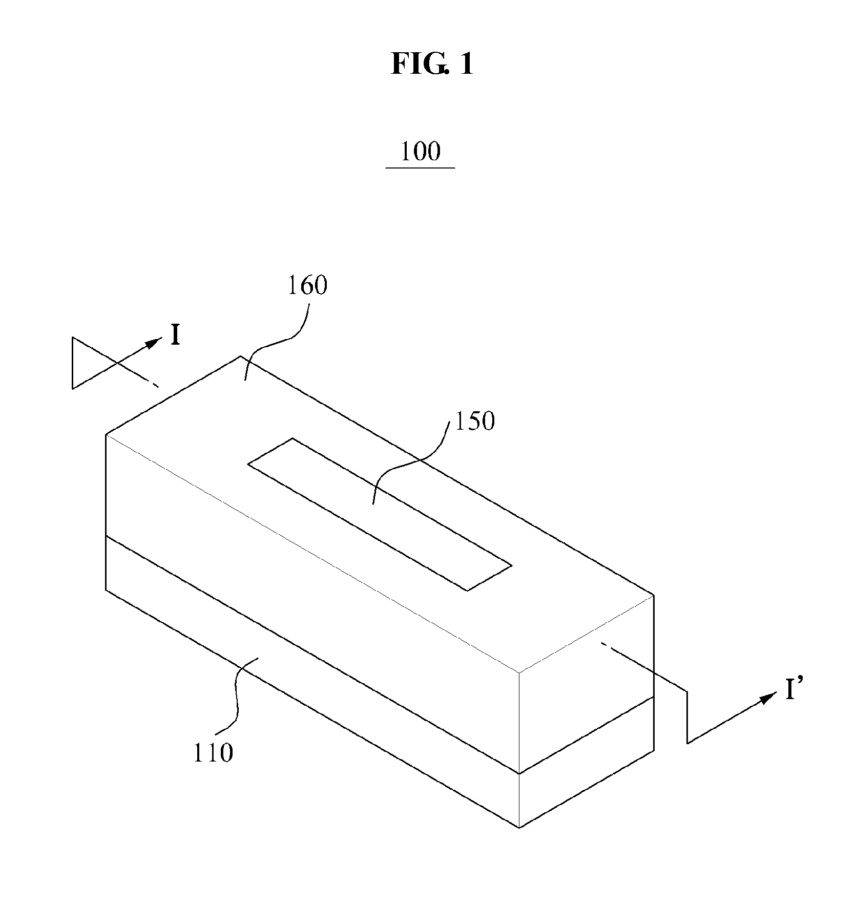
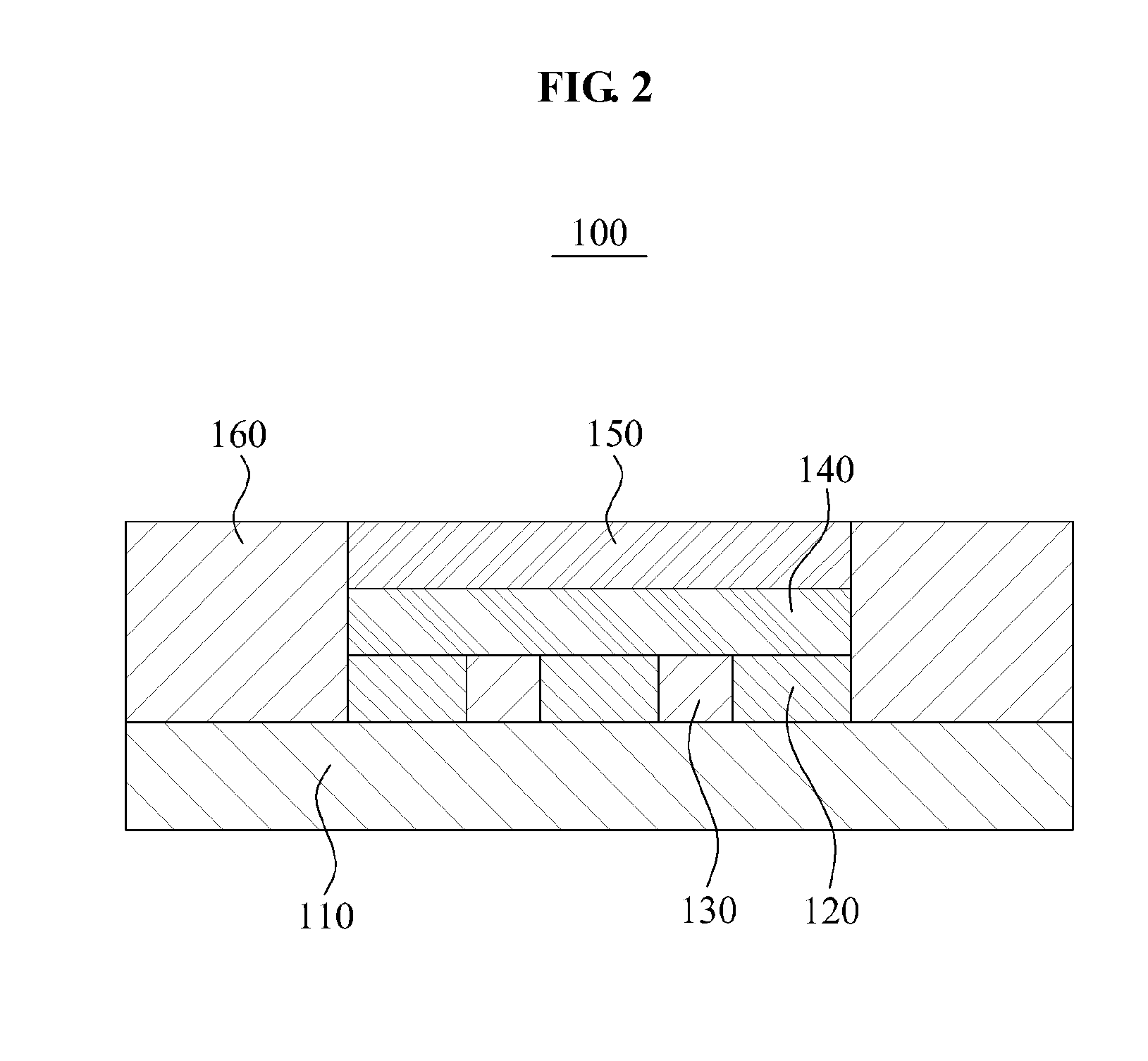
[0035]Reference will now be made in detail to exemplary embodiments of the present invention, examples of which are illustrated in the accompanying drawings, wherein like reference numerals refer to the like elements throughout. Exemplary embodiments are described below to explain the present invention by referring to the figures.

[0036]Throughout the specifications, when it is described that each of a substrate, a layer, an element, and the like is formed “on” or “under” a substrate, a layer, an element, and the like, the term “on” may include “directly on” and “indirectly on interposing another element therebetween,” and the term “under” may include “directly under” and “indirectly under interposing another element therebetween.” A standard for “on” or “under” of each element may be determined based on a corresponding drawing.

[0037]Sizes of elements in drawings may be exaggerated for ease of descriptions, and do not indicate real sizes.

[0038]Hereinafter, a light emitting device (LE...


PUM


Abstract

An LED assembly according to an embodiment of the present invention may improve dark regions generated between LED chips by employing a first reflective layer between the LED chips. By employing a transparent optical layer or an optical layer including a scattering particle between an LED chip and a phosphor layer, direct contact between the LED chip and the phosphor layer may be avoided, thereby preventing a low light extraction efficiency. Further, by employing a second reflection layer on side surfaces of an LED chip, an optical layer, and a phosphor layer, a relatively high contrast may be obtained. An LED assembly may enhance contrast through a reflective layer while increasing light extraction efficiency by including a scattering particle in a phosphor layer.

Description

CROSS-REFERENCE TO RELATED APPLICATION[0001]This application claims the benefit of Korean Patent Application No. 10-2011-0046845, filed on May 18, 2011, in the Korean Intellectual Property Office, the disclosure of which is incorporated herein by reference.BACKGROUND[0002]1. Field of the Invention[0003]The present invention relates to a light emitting device (LED) assembly and a headlamp including the LED assembly, and more particularly, to an LED assembly and a headlamp including the LED assembly that may obtain high contrast while reducing a loss of light emitted from an LED.[0004]2. Description of the Related Art[0005]In general, a vehicle may incorporate a lamp system such as a headlamp and a tail lamp to recognize an object in a traveling direction while travelling at night and to inform other vehicles or other load users about a travel state of the vehicle. The headlamp may be referred to as a headlight, and indicate a lighting lamp that lights a path along which the vehicle t...

Claims


Application Information

Patent Timeline
IPC IPC(8): F21V13/04H01L33/60
CPCH01L33/50H01L33/507H01L33/46H01L33/44H01L33/60F21S48/1154H01L2933/0091H01L33/501F21S41/255F21S41/32F21S41/323F21S41/37F21S41/16F21S41/145F21S41/176F21S41/00F21V7/24F21K2/00F21Y2115/10F21W2102/00
Inventor KIM, HEE DONGPARK, MOO YOUNLEE, SOO HWANPARK, HEE SEOK
Owner SAMSUNG ELECTRONICS CO LTD
Why Eureka
Try Eureka