Detector

A detector and light-receiving component technology, applied in the field of sensors, can solve problems such as difficult-to-wear positions, increased probability of picking up interfering light, and increased light quantity, and achieves the effects of easy-to-wear positions, improved light-receiving efficiency, and easy calibration.

Inactive Publication Date: 2007-02-28
SHARP KK
View PDF1 Cites 10 Cited by
  • Summary
  • Abstract
  • Description
  • Claims
  • Application Information

AI Technical Summary

Problems solved by technology

[0011] In the reflective ring sensor disclosed in JP 2002-224088A, since reflected light or scattered light is received, the light receiving efficiency is poor, so it is necessary to increase the amount of light emitted by the light emitting part, or to enlarge the light receiving part corresponding to the light emitting part. light receiving area
Increasing the amount of light will cause low-temperature burns to the human body when worn for a long time
[0012] In the case of enlarging the receiving area of ​​a single light receiving part, the probability of picking up disturbance light (which is not the object of measurement) increases, and this causes a problem of low signal-to-noise ratio
[0013] In addition, when detecting the pulse waveform, there is a problem that the signal-to-noise ratio is low depending on the wearing position
Also, due to the shape of the ring, body movement can severely misalign the ring sensor in the direction of rotation
In this case, the AC component drops, which causes low signal-to-noise ratio problems
[0014] In addition, with a single light receiving part, it is difficult to determine whether the wearing position is optimal, and it is impossible to detect the direction in which the wearing position is misaligned

Method used


Image

  • Detector
  • Detector
  • Detector

Examples


Embodiment 1

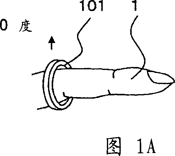
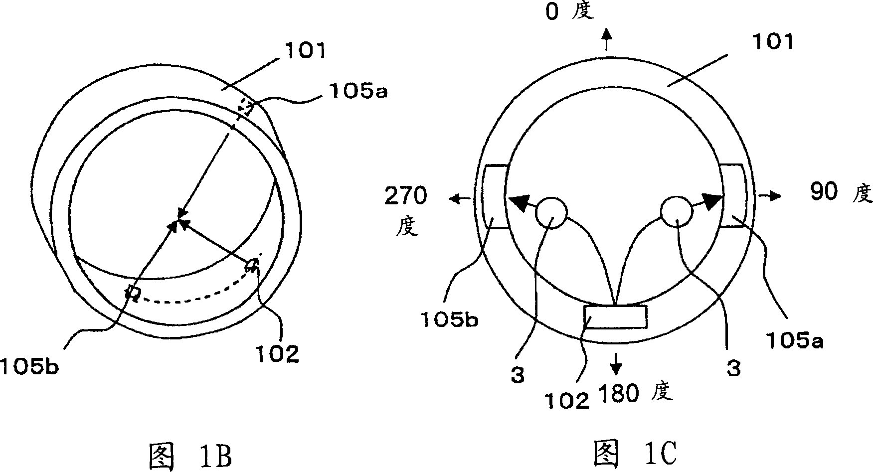
[0057] 1A to 1E are the finger ring sensor in Embodiment 1.

[0058]As shown in FIG. 1A , a ring sensor 101 which is a finger-ring type ring is worn on the base of a finger. The size of the ring is properly selected according to the size of each user's finger, so that the inner peripheral surface of the ring is always in close contact with the finger.

[0059] 1B and 1C show the inner peripheral surface and cross-section of the ring sensor. On the inner peripheral surface, there are a light emitting part 102 constituted by a light emitting diode, and first and second light receiving parts 105a, 105b constituted by a photodiode. The light emitting part 102 has a light emitting diode emitting red light and a light emitting diode emitting infrared light.

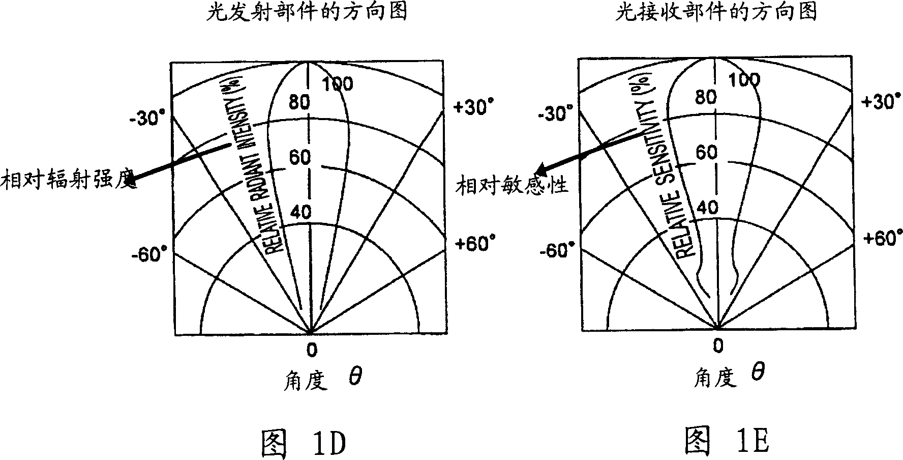
[0060] Fig. 1D shows a directional diagram of a light-emitting part and a light-receiving part. The light-emitting component 102 and the corresponding light-receiving component 105 have the maximum relative radiation intensi...

Embodiment 2

[0097] 3A to 3D are the ring sensor in Embodiment 2.

[0098] It should be noted that for the structure of Embodiment 2, explanations about the same structural components as in Embodiment 1 shown in FIGS. 1A to 1E and FIGS. 2A to 2B are omitted, and their differences are mainly described.

[0099] 3A and 3B, the light emitting part 202 is formed on the inner peripheral surface of the ring sensor 201, and the first and second light receiving parts 205a, 205b are formed at positions symmetrical to the light emitting axis of the light emitting part 202. Specifically, the first and second light receiving members 205 a , 205 b are placed at positions facing each other on the inner peripheral surface of the ring sensor 201 .

[0100] In addition, the light-emitting point of the light-emitting part 202 and the respective light-receiving points of the first and second light-receiving parts 205a, 205b are placed on tracks different from each other on the inner peripheral surface of the...

Embodiment 3

[0105] FIG. 4A is a perspective view showing a worn state of a finger-ring sensor in Embodiment 3 of the present invention, and FIG. 4B is a cross-sectional view showing the finger-ring sensor.

[0106] It should be noted that for the structure of Embodiment 3, explanations about the same structural components as in Embodiments 1 and 2 shown in FIGS. 1A to 1E and FIGS. 3A to 3D are omitted, and their differences are mainly described.

[0107] The first and second light receiving members 305a, 305b are divided into light receiving areas a, b, c and A, B, C, respectively.

[0108] Each light-receiving area is formed in the order of a, b, c and A, B, C along the inner circumferential surface of the ring, starting from the farthest side from the light-emitting part 302 in the circumferential direction.

[0109] In FIG. 4B , the light emitting part 302 is formed on the inner peripheral surface of the ring sensor 301 , and the first and second light receiving parts 305 a , 305 b are...


PUM


Abstract

A pair of light-receiving sections are placed at positions symmetric to a light-emitting axis of a light-emitting section on the inner circumferential surface in close contact with a finger, and each light-receiving section is composed of a plurality of light receiving regions so that by selecting a signal of the light receiving region which maximizes a reception signal, the propriety and the correction direction of a wearing position are displayed. According to the ring sensor, it becomes possible to enhance light-receiving efficiency of the light-receiving section and to increase a signal-noise ratio. It also becomes possible to facilitate wearing of the ring sensor at an optimum position.

Description

technical field [0001] The present invention relates to sensors for measuring biological information by optical means in a non-invasive manner. Background technique [0002] Conventionally, a ring sensor having a light-emitting part and a light-receiving part on the inner peripheral surface of the ring has been used to detect the pulse waveform by optical means. [0003] It is known that among hemoglobin of blood, oxyhemoglobin and reduced hemoglobin differ in light absorption and transmission characteristics depending on the wavelength of light. Oxyhemoglobin absorbs more infrared light than red light, while the optical property of reduced hemoglobin is that it absorbs more red light than infrared light. [0004] Therefore, by wearing a ring sensor on the finger and pressing the light receiving part and the light emitting part against the finger, a specific pressure is applied to the blood vessels on the finger in advance. During the vasoconstriction period, the amount of ...

Claims


Application Information

Patent Timeline
Patent Type & Authority Applications(China)
IPC IPC(8): A61B5/00A61B5/0245
CPCA61B5/14552A61B5/6826A61B5/6838A61B5/14
Inventor 大石嘉弘
Owner SHARP KK
Why Eureka
Try Eureka