Optical information analysis device and optical information analysis method

A technology for analyzing devices and optical information, applied in measuring devices, analytical materials, individual particle analysis, etc., can solve problems such as deviation of optical information, inability to adjust the optical axis of the irradiation part, and non-intersection of optical axes

Active Publication Date: 2014-04-09
雅马拓科学株式会社
View PDF5 Cites 0 Cited by
  • Summary
  • Abstract
  • Description
  • Claims
  • Application Information

AI Technical Summary

Problems solved by technology

[0005] However, in the above-mentioned conventional device, there is a problem that when the sample flow passes through a position deviated from the center of the flow path in the flow cell, the optical axis of the irradiating part coincides with the sample flow. The optical axis of the optical system of the part does not cross the optical axis of the sample flow and the irradiation part
Therefore, the light receiving unit is configured to receive light in a wide range. As a result, the sensitivity of detected scattered light and fluorescence decreases, or the obtained optical information of the specimen varies.
[0006] In addition, there is a problem that the optical axis of the irradiation part cannot be adjusted and the optical axis of the irradiation part cannot be adjusted easily because the sample flow is actually produced only by flowing the liquid in the flow channel in the flow cell.

Method used


Image

  • Optical information analysis device and optical information analysis method
  • Optical information analysis device and optical information analysis method
  • Optical information analysis device and optical information analysis method

Examples


Embodiment Construction

[0081] Hereinafter, embodiments of the present invention will be described in detail based on the drawings.

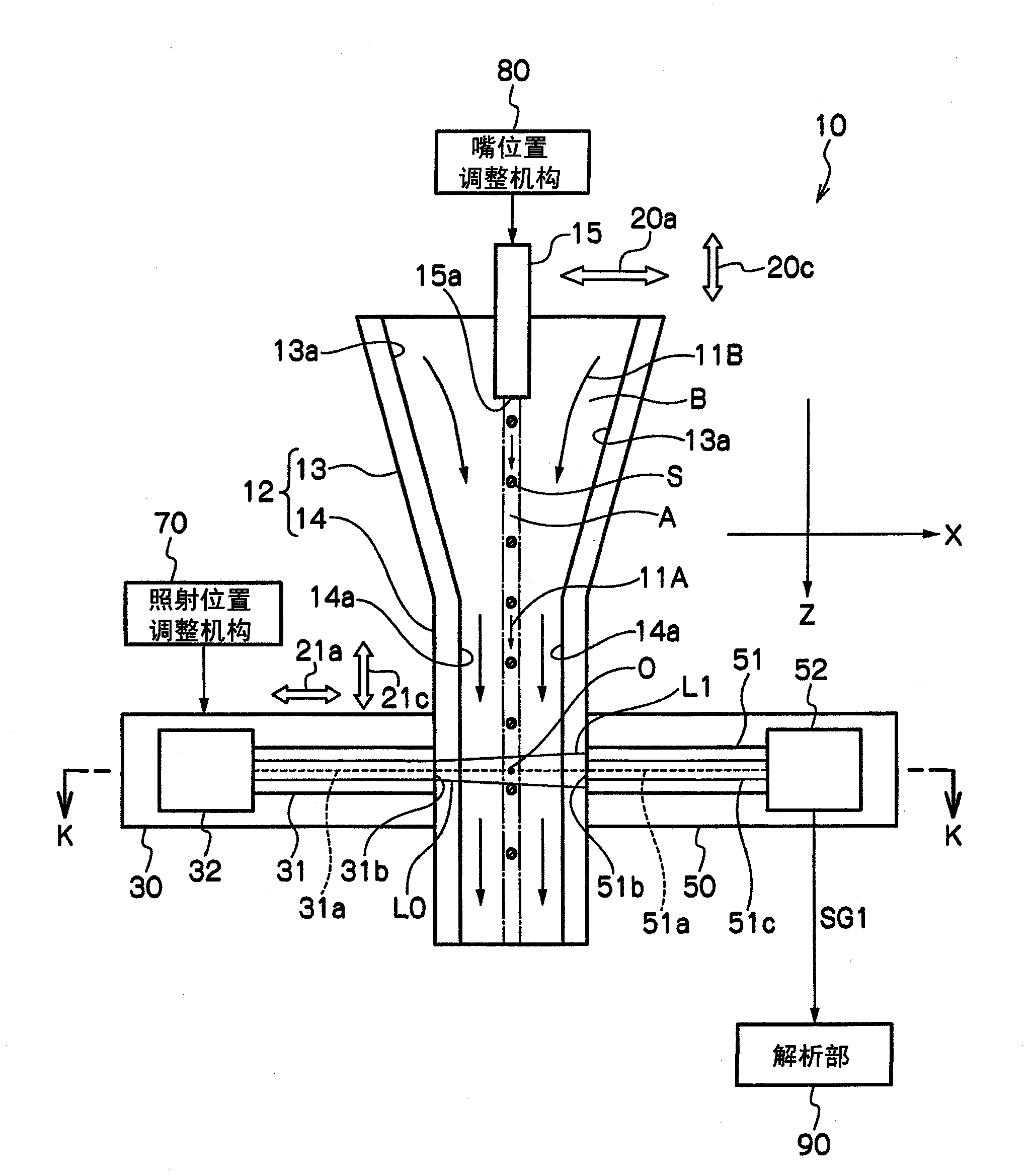
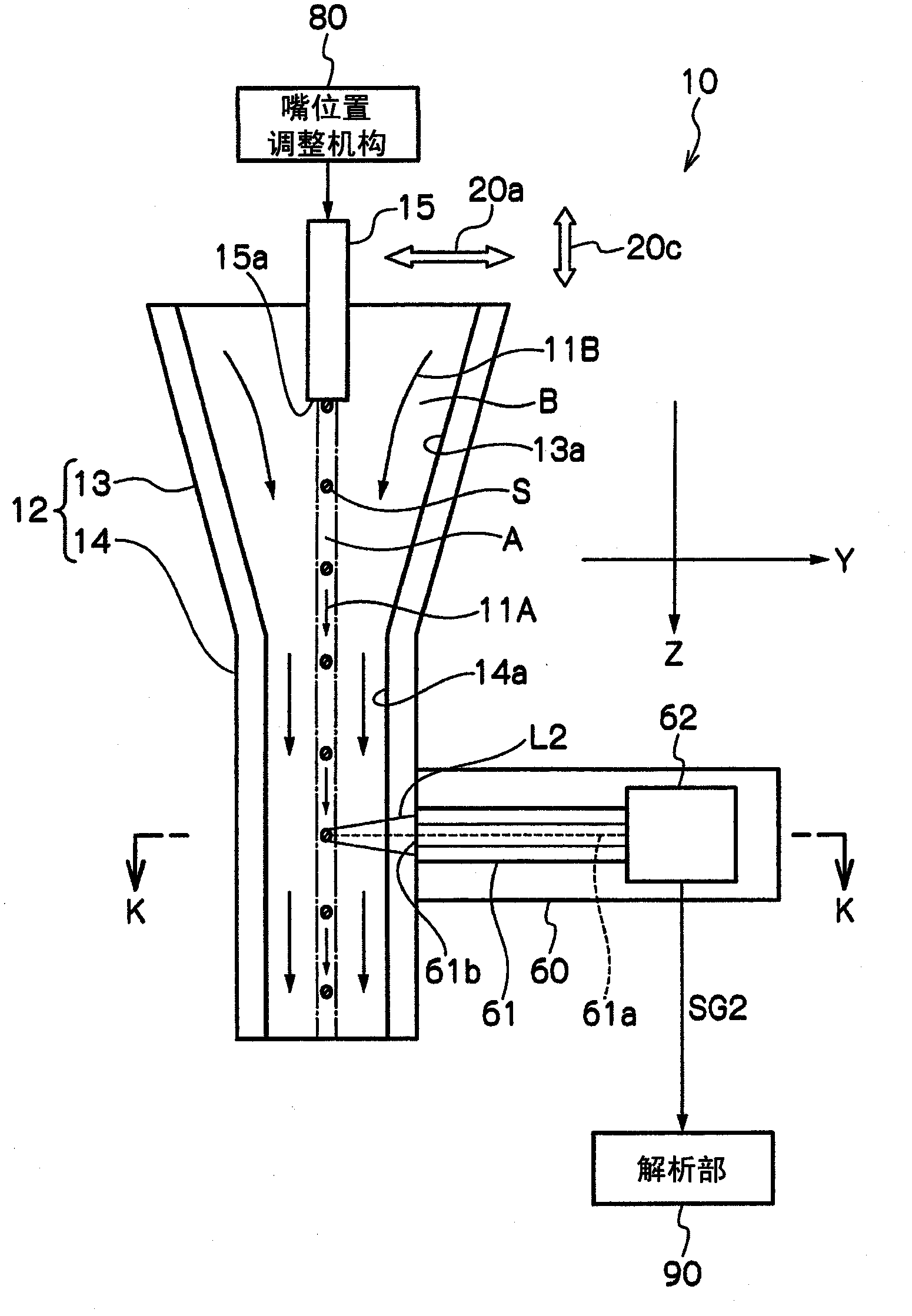
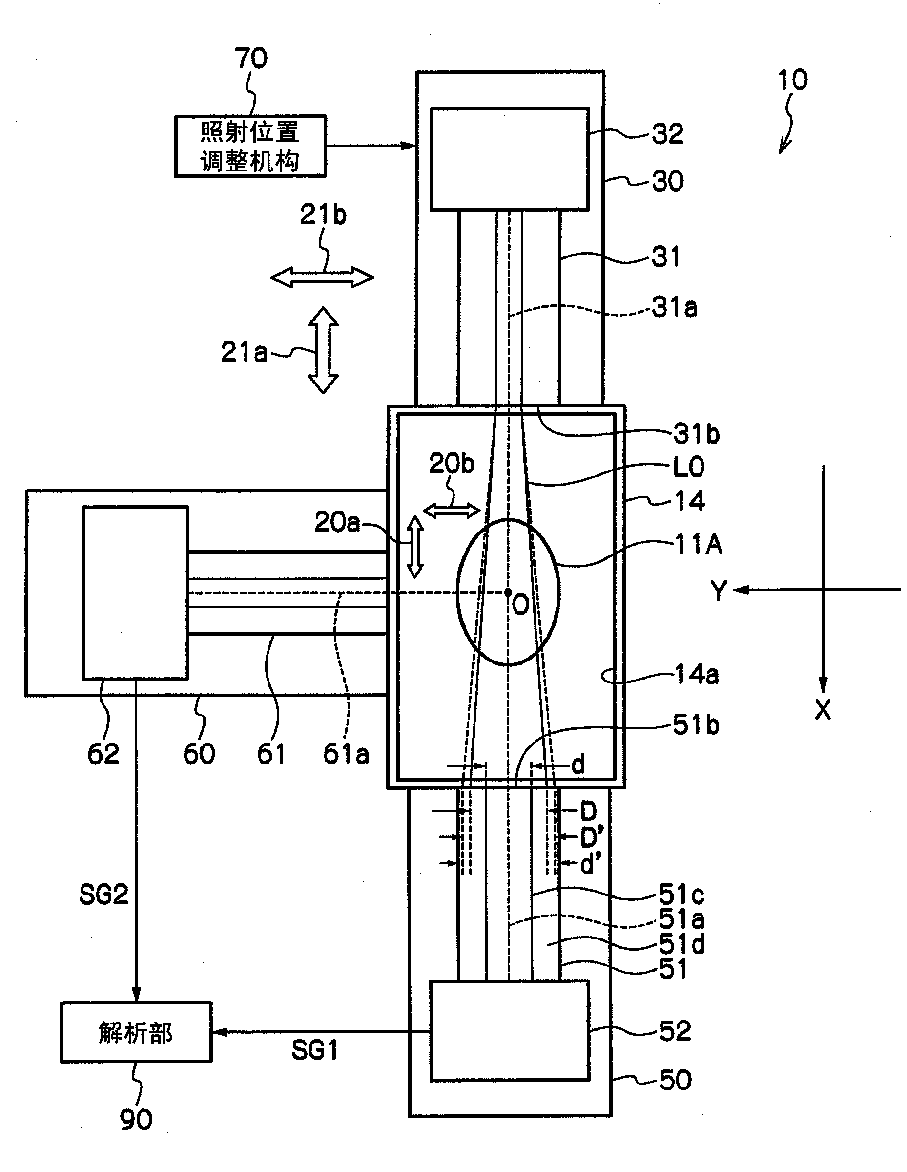
[0082] figure 1 It is a schematic longitudinal sectional view of an optical information analysis device according to an embodiment of the present invention. in addition, figure 2 is to make figure 1 A schematic longitudinal sectional view of the optical information analysis device rotated 90 degrees around the Z axis, image 3 yes figure 1 and figure 2 A schematic cross-sectional view of the K-K line of the optical information analysis device.

[0083] Such as Figure 1 ~ Figure 3As shown, an optical information analysis device 10 according to an embodiment of the present invention includes: a flow cell 12 having a flow path 13a and a flow path 14a through which a liquid A flows; 13a introduces an introduction nozzle 15 for introducing liquid A; an irradiation unit 30 for irradiating a single-mode irradiation light (excitation light) L0 to the specimen S dispe...


PUM


Abstract

An optical information analyzing device includes an irradiating unit that irradiates irradiation light to specimens, a transmitted light receiving unit that receives transmitted light and detects the transmitted light as a transmitted light signal, a scattering / fluorescent light receiving unit that receives lateral scattering light and fluorescent light and detects the lateral scattering light and the fluorescent light as a scattering / fluorescent light signal, a nozzle position adjusting mechanism, and an analyzing unit that measures the optical information on the specimen on the basis of the detected transmitted light signal and the detected scattering / fluorescent light signal and analyzes the specimen.

Description

technical field [0001] The present invention relates to an optical information analysis device and an optical information analysis method. In particular, it relates to an optical information analysis device and an optical information analysis method for measuring optical information of a sample by irradiating irradiation light on a sample to be measured that is dispersed in a liquid flowing in a flow channel. Background technique [0002] Proposals include the following devices (flow type position meter (flow type position meter), cell sorting instrument) in which a liquid containing biological particles (microscopic objects to be tested: specimen) that has been stained is placed in a flow path The flow channel forming the member (fluid cell) flows, the light irradiated from the illuminating unit (irradiating unit) contacts the biological particles, and the scattered light from the biological particles is detected by the detecting unit (light receiving unit). and fluorescen...

Claims


Application Information

Patent Timeline
Patent Type & Authority Patents(China)
IPC IPC(8): G01N15/14
CPCG01N15/1434G01N2015/1452
Inventor 月井健木村健一高桥亨徐杰
Owner 雅马拓科学株式会社
Why Eureka
Try Eureka