A light receiving method, device and system

A light-receiving device and light-receiving technology, applied in the field of optics, can solve the problems of narrow angle of light signal received by convex lens, high reflectivity of convex lens, reduction of light-receiving efficiency, etc. The effect of loss

Active Publication Date: 2018-07-10
THE PLA INFORMATION ENG UNIV
View PDF11 Cites 0 Cited by
  • Summary
  • Abstract
  • Description
  • Claims
  • Application Information

AI Technical Summary

Problems solved by technology

[0004] However, the angle at which the convex lens receives light signals is relatively narrow, and usually can only receive light signals that are vertically incident or close to vertically incident; moreover, the reflectivity of the convex lens is relatively high, resulting in the loss of light energy, thereby reducing the light receiving efficiency

Method used


Image

  • A light receiving method, device and system
  • A light receiving method, device and system
  • A light receiving method, device and system

Examples


Embodiment Construction

[0034] At present, the optical receiving system generally collects optical signals through a convex lens, so it has the following disadvantages: 1. The angle at which the convex lens receives optical signals is relatively narrow, and usually can only receive optical signals that are vertically incident or close to vertically incident; 2. The reflection of the convex lens The efficiency is also relatively high, resulting in the loss of light energy, thereby reducing the light receiving efficiency; 3. The thickness of the convex lens is relatively large, which is not conducive to the thin and light design of the device.

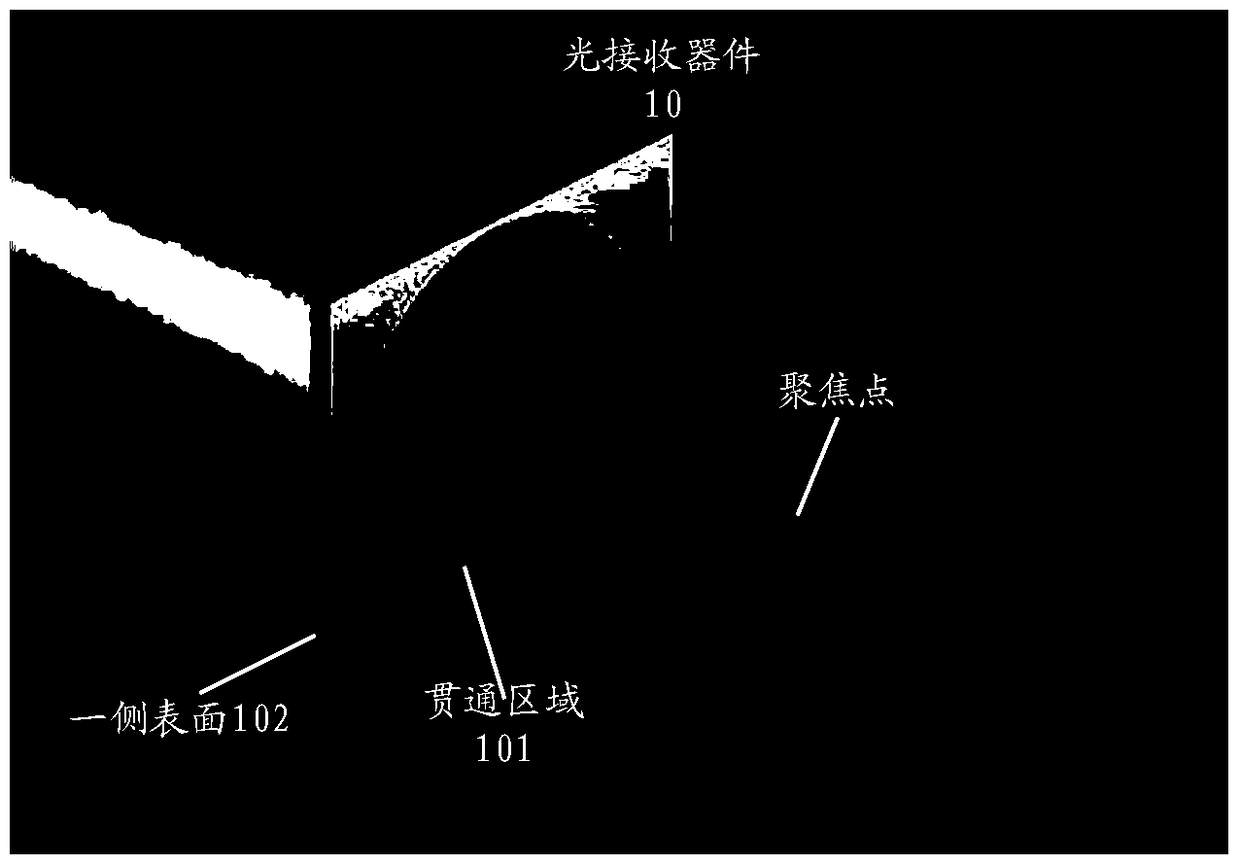
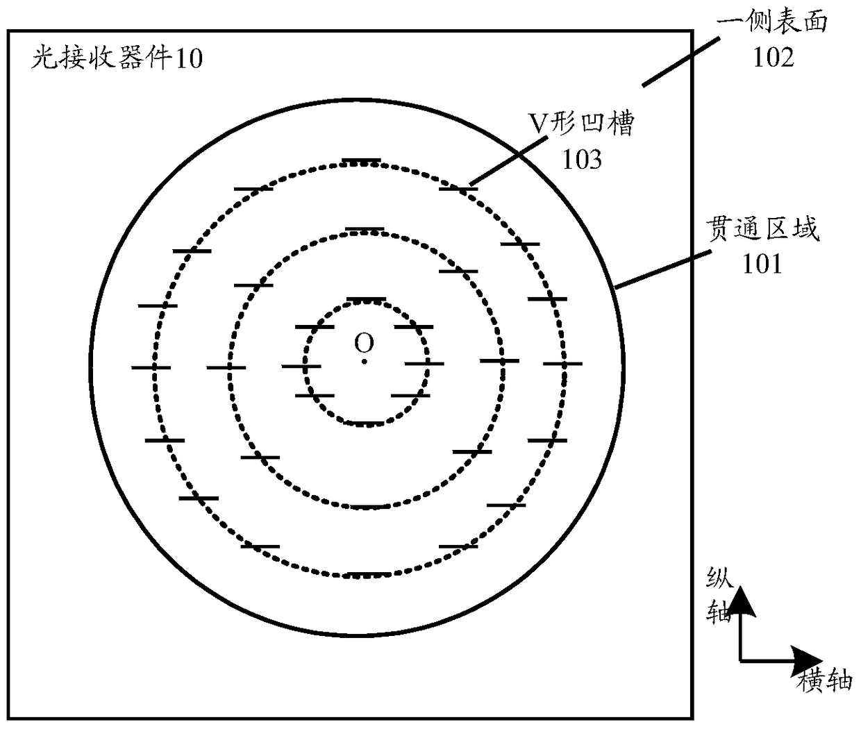
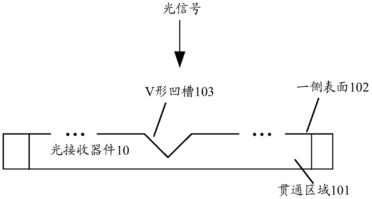
[0035] Embodiments of the present invention provide a light receiving method, device and system, so as to increase the light receiving angle and reduce the loss of light energy, thereby improving the light receiving efficiency. In addition, compared with the convex lens, it also has the advantage of smaller thickness, which is more conducive to the thin and ligh...


PUM


Abstract

The embodiment of the invention provides a light reception method, device and system. The light reception device is of a slab structure, comprising a through area adopting light transmission materials. One side surface, used for receiving light signals, of the through area is provided with a plurality of V-shaped grooves. The plurality of V-shaped grooves are arranged to form at least two concentric circles. The opening direction of each V-shaped groove faces towards an incident direction of the light signals, and the surface, facing the incident direction, of each V-shaped groove employs a micro-nano optical structure. The through area is used for receiving the light signal through the side surface, and carries out focusing of the light signals through utilization of the plurality of V-shaped grooves. Evidently, the light reception device can receive the incident light signals in a certain angle scope through utilization of the plurality of V-shaped grooves. Compared with a convex lens, the light reception device enlarges the light reception angle. Furthermore, the surface, facing the incident direction, of each V-shaped groove employs the micro-nano optical structure, so that loss of luminous energy can be reduced and the light reception efficiency can be raised.

Description

technical field [0001] The invention relates to the field of optics, in particular to a light receiving method, device and system. Background technique [0002] The optical communication system includes an optical transmitting system and an optical receiving system. The optical transmitting system is used to load the information to be transmitted onto an optical signal (such as an optical signal in the visible light band) and transmit it; the optical receiving system is used to receive the information emitted by the optical transmitting system. The optical signal is converted into a corresponding electrical signal and then analyzed to obtain the transmitted information. [0003] At present, the light receiving system generally includes a convex lens, a photodetector, and a signal processing circuit. The convex lens receives the optical signal and focuses it on the photodetector, and the photodetector converts the collected optical signal into a corresponding electrical signa...

Claims


Application Information

Patent Timeline
Patent Type & Authority Patents(China)
IPC IPC(8): G02B6/42H04B10/67
CPCG02B6/4206G02B6/423G02B6/4286H04B10/67
Inventor 朱义君孙正国
Owner THE PLA INFORMATION ENG UNIV
Why Eureka
Try Eureka