Photovoltaic power generation device with assembly easy-to-install structure

An installation structure and photovoltaic power generation technology, applied in the direction of photovoltaic power generation, photovoltaic modules, photovoltaic module support structures, etc., can solve the problems of lack of photovoltaic panels and laborious installation of existing devices, and achieve the effect of convenient use and improved convenience.

Pending Publication Date: 2021-09-03
魏雅倩
View PDF0 Cites 0 Cited by
  • Summary
  • Abstract
  • Description
  • Claims
  • Application Information

AI Technical Summary

Problems solved by technology

[0005] The present invention provides a photovoltaic power generation device with an easy-to-install structure of components, one of which is to provide a function for users to install conveniently, and to solve the problem of laborious installation of existing devices; the other purpose is to solve the problem of existing The photovoltaic power generation device does not have the function of cooling the top of the photovoltaic panel, so as to reduce the probability of damage to the internal components of the photovoltaic panel due to high temperature

Method used


Image

  • Photovoltaic power generation device with assembly easy-to-install structure
  • Photovoltaic power generation device with assembly easy-to-install structure
  • Photovoltaic power generation device with assembly easy-to-install structure

Examples


Embodiment 1

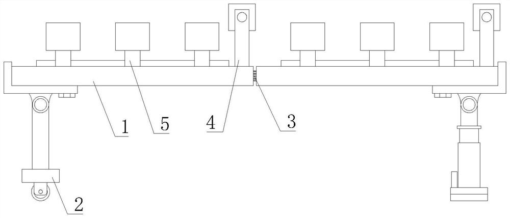
[0044] Such as Figure 1-7As shown, the present invention provides a photovoltaic power generation device with an easy-to-install structure for components, including a mounting structure plate 1, a photovoltaic panel body 6 is fixedly installed on the top of the mounting structure plate 1, and an angle adjustment mechanism is provided at the bottom of the mounting structure plate 1 2. A connecting mechanism 3 is provided on the outer wall of the installation structure plate 1, a sprinkler mechanism 4 is installed on the top of the installation structure plate 1, and a reflective mechanism 5 on the left side of the sprinkler mechanism 4 is arranged on the top of the installation structure plate 1.

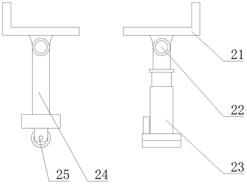
[0045] The angle adjustment mechanism 2 includes a mounting seat 21, which is movably connected to the bottom of the mounting structure plate 1, and the bottom of the mounting seat 21 is rotatably connected with a hinge 22, and the bottom of the hinge 22 on the left side is fixedly e...

Embodiment 2

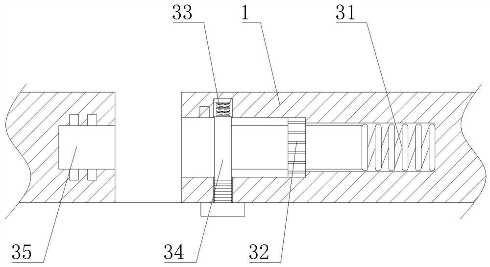
[0050] Such as Figure 1-7 As shown, on the basis of Embodiment 1, the present invention provides a technical solution: preferably, an electric push rod 23 is fixedly installed at the bottom of the hinge 22 on the right side, and the bottom of the electric push rod 23 is rotatably connected to the ground , the fixed mechanism 32 includes a connecting steel pipe 321, the connecting steel pipe 321 is fixedly installed on the left side of the snap spring 31, the middle part of the connecting steel pipe 321 is provided with a fixed runner 322, and both sides of the fixed runner 322 are fixedly connected with a transmission rod 323, the transmission The side of the rod 323 away from the fixed runner 322 is fixedly connected with a gear 324, and the back side connected to the inner cavity of the steel pipe 321 is fixedly installed with a bottom plate 325, and the front side of the bottom plate 325 is slidingly connected with a rack 326, and the front side of the rack 326 meshes with ...

Embodiment 3

[0053] Such as Figure 1-7 As shown, on the basis of Embodiment 1, the present invention provides a technical solution: preferably, a water outlet hole 44 is provided on the outer wall of the rotating cooling pipe 43, and a pressurized bag 46 is fixedly installed on the inner wall of the rotating cooling pipe 43, The inner cavity of the pressurized bag 46 is filled with helium.

[0054] In this embodiment, the combination of the rotary cooling tube 43 and the pressurized bag 46 is adopted. Before the pure water enters the inner cavity of the rotary cooling tube 43, the nitrogen in the pressurized bag 46 is heated by the sun and expands to drive the pressurized bag. The increase in volume of 46 impels the volume of the inner cavity of the rotating cooling pipe 43 to decrease, so that the water pressure ejected from the water outlet hole 44 becomes larger, and the stronger dust attached to the surface of the photovoltaic panel body 6 can be cleaned up. After the nitrogen in the...


PUM


Abstract

The invention discloses a photovoltaic power generation device with a component easy installation structure and relates to the technical field of photovoltaic power generation. The photovoltaic power generation device comprises an installation structure plate, wherein the top of the installation structure plate is fixedly provided with a photovoltaic panel body, the bottom of the installation structure plate is provided with an angle adjusting mechanism, and an outer wall of the installation structure plate is provided with a connecting mechanism; and a water sprinkling mechanism is arranged at the top of the mounting structure plate. Through the design of rotating a limiting rod and a booster spring, after the limiting rod rotates, the limiting rod can be popped out of the bottom of the mounting structure plate, the booster spring can be conveniently taken out, then under the action of elasticity of a clamping spring, a fixing mechanism is popped out, the left side of the fixing mechanism is inserted into a connecting groove, and then a fixed rotating wheel is rotated; and clamping blocks are promoted to be clamped in the corresponding groove holes, so the splicing work of the mounting structure plates is completed, and a problem that an existing device is strenuous to mount is solved.

Description

technical field [0001] The invention relates to a photovoltaic power generation device, relates to the technical field of photovoltaic power generation, and in particular to a photovoltaic power generation device with a structure for easy installation of components. Background technique [0002] Photovoltaic power generation is a technology that directly converts light energy into electrical energy by using the photovoltaic effect of the semiconductor interface. It is mainly composed of three parts: solar panels, controllers and inverters. The main components are composed of electronic components. Solar cells Encapsulation and protection after being connected in series can form a large-area solar cell module, and then cooperate with power controllers and other components to form a photovoltaic power generation device. There are following problems at prior art: [0003] 1. The existing photovoltaic power generation devices are mostly spliced ​​and installed by various tools ...

Claims


Application Information

Patent Timeline
Patent Type & Authority Applications(China)
IPC IPC(8): H02S40/42H02S40/10H02S20/30H02S40/22A01M29/10B08B3/02B08B13/00
CPCH02S40/42H02S40/10H02S20/30H02S40/22A01M29/10B08B3/02B08B13/00Y02E10/52
Inventor 魏雅倩
Owner 魏雅倩
Why Eureka
Try Eureka