Light emitting device and light irradiation apparatus including the same

Active Publication Date: 2018-06-28
NICHIA CORP
View PDF0 Cites 6 Cited by
  • Summary
  • Abstract
  • Description
  • Claims
  • Application Information

AI Technical Summary

Benefits of technology

[0009]According to the aforementioned light emitting device which includes a light-transmissive member having semi-cylindrical lens portions arranged side by side transversely, the maximum slope of the light-intensity-distribution curve of the light emitting device in the transve

Problems solved by technology

In this case, the inside part of the ink, resi

Method used


Image

  • Light emitting device and light irradiation apparatus including the same
  • Light emitting device and light irradiation apparatus including the same
  • Light emitting device and light irradiation apparatus including the same

Examples


Example

First Embodiment

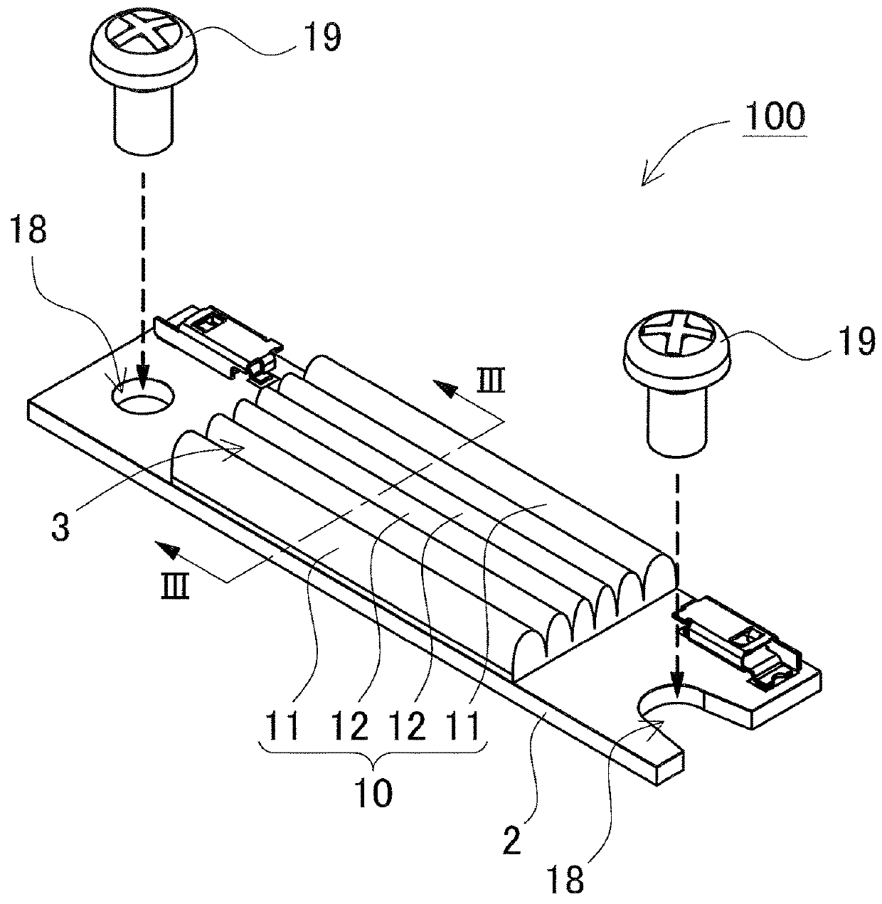
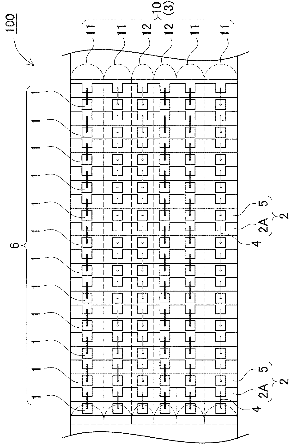
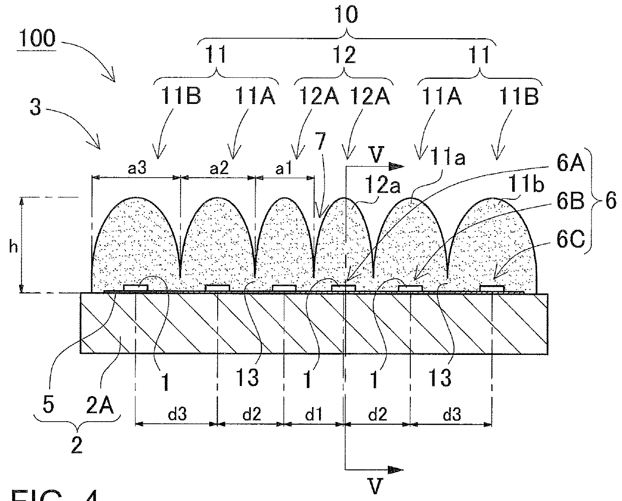
[0027]A light emitting device 100 according to a first embodiment of the present invention is shown in FIGS. 1 to 5. FIG. 1 is a perspective view schematically showing the light emitting device 100 according to the first embodiment. FIG. 2 is a plan view schematically showing the arrangement of light emitting elements 1 of the light emitting device 100 shown in FIG. 1. FIG. 3 is a cross-sectional view schematically showing the light emitting device 100 shown in FIG. 1 taken along the line III-III. FIG. 4 is a graph showing the light-intensity-distribution curve of the light emitting device 100 shown in the schematic cross-sectional view of FIG. 3. FIG. 5 shows cross-sectional and partially enlarged cross-sectional views schematically showing the light emitting device 100 shown in FIG. 3 taken along the line V-V.

[0028]The light emitting device 100 includes a printed board 2, the light emitting elements 1, and a light-transmissive member 3. The light emitting elements ...

Example

Second Embodiment

[0060]A light emitting device 200 according to a second embodiment is now described with reference to drawings. FIG. 6 is a cross-sectional view schematically showing the light emitting device 200 according to the second embodiment. FIG. 7 is a cross-sectional view showing a principal part of the light emitting device 200 shown in FIG. 6.

[0061]The light emitting device 200 according to the second embodiment includes a light-transmissive member 23 having a shape different from the light-transmissive member 3 according to the first embodiment. The light-transmissive member 23 consists of six semi-cylindrical lens portions 10 which are coupled by the connection parts 13 to each other similar to the light-transmissive member 3 according to the first embodiment. First semi-cylindrical lens portions 11C and 11D are semi-cylindrical lens portions which are arranged to cover the light emitting elements in the both end rows (outermost rows in the parallel arrangement directi...

Example

Third Embodiment

[0071]A light emitting device 300 according to a third embodiment is now described with reference to drawings. FIG. 8 is a cross-sectional view schematically showing the light emitting device 300 according to the third embodiment.

[0072]The light emitting device 300 includes the light-emitting-element rows 6 which are arranged on the printed board 2 and are spaced at a fixed interval away from each other, and a light-transmissive member 33 including semi-cylindrical lens portions 10 which are arranged side by side transversely on their corresponding light-emitting-element rows 6. In the case where the light-emitting-element rows 6 are spaced at a substantially fixed interval away from each other, the light emitting elements 1 can be easily mounted. The term “substantially fixed interval” refers to intervals the difference of which falls within the range not greater than 2.0 mm.

[0073]In the light emitting device 300 according to the third embodiment, the shapes of the ...


PUM


Abstract

A light emitting device is provided which includes a printed board, light emitting elements, and a light-transmissive member. The light emitting elements are arranged in three or more rows, and mounted on the printed board. The light-transmissive member includes three or more semi-semi-cylindrical lens portions that are arranged side by side transversely to cover the three or more rows. The heights of the tops of the semi-cylindrical lens portions are substantially equal to each other. The semi-cylindrical lens portions include first semi-cylindrical lens portions which are arranged to cover at least the both end rows, and a second semi-cylindrical lens portion which is arranged on the interior sides relative to the first semi-cylindrical lens portions in the transverse direction. The radius of curvature of the second semi-cylindrical lens portion is smaller than the first semi-cylindrical lens portions.

Description

CROSS-REFERENCE TO RELATED APPLICATIONS[0001]The present application claims priority under 35 U. S. C. § 119 to Japanese Patent Application No. 2016-253,815 filed on Dec. 27, 2016. The contents of this application are incorporated herein by reference in their entirety.BACKGROUND OF THE INVENTION1. Field of the Invention[0002]The present disclosure relates to a light emitting device, and a light irradiation apparatus which includes the light emitting devices.2. Description of the Related Art[0003]A COB (Chip On Board) type of light emitting device is known which includes light emitting diodes (hereinafter, also referred to as LEDs) as light emitting elements. For example, a light emitting device is known which includes light emitting elements mounted on a printed board, and a light-transmissive sealing member which has semi-semi-cylindrical lens portions connected to each other. Each of the semi-semi-cylindrical lens portions covers corresponding one of rows of light emitting element...

Claims


Application Information

Patent Timeline
IPC IPC(8): B05D3/06H01L25/075H01L33/62H01L33/58H01L33/46F21V5/00F21V5/04
CPCB05D3/067H01L25/0753H01L33/62H01L33/58H01L33/46F21V5/007F21V5/043F21Y2105/16F21Y2115/10H01L33/54
Inventor AIZAWA, TOSHIHIKOONO, MASATOKISHIKAWA, DAISUKE
Owner NICHIA CORP
Why Eureka
Try Eureka