Sunlight readable LCD with uniform in-cell retarder

a technology of in-cell retarder and sunlight readable lcd, which is applied in the field of consumer electronic displays, can solve the problems of long battery life requirements, reflection and transflective display types are retreated, etc., and achieve the effects of improving the appearance of high ambient lighting, low ambient light image quality, and high quality

Active Publication Date: 2017-02-02
SHARP KK
View PDF6 Cites 71 Cited by
  • Summary
  • Abstract
  • Description
  • Claims
  • Application Information

AI Technical Summary

Benefits of technology

[0006]It is therefore desirable to provide an LC display in which an LC mode configuration typically used in conjunction with linear polarisers for optimum low ambient light image quality is utilised with a circular front polarise...

Problems solved by technology

This has resulted in the retreat of reflective and transflective display types into niche ...

Method used


Image

  • Sunlight readable LCD with uniform in-cell retarder
  • Sunlight readable LCD with uniform in-cell retarder
  • Sunlight readable LCD with uniform in-cell retarder

Examples


Embodiment Construction

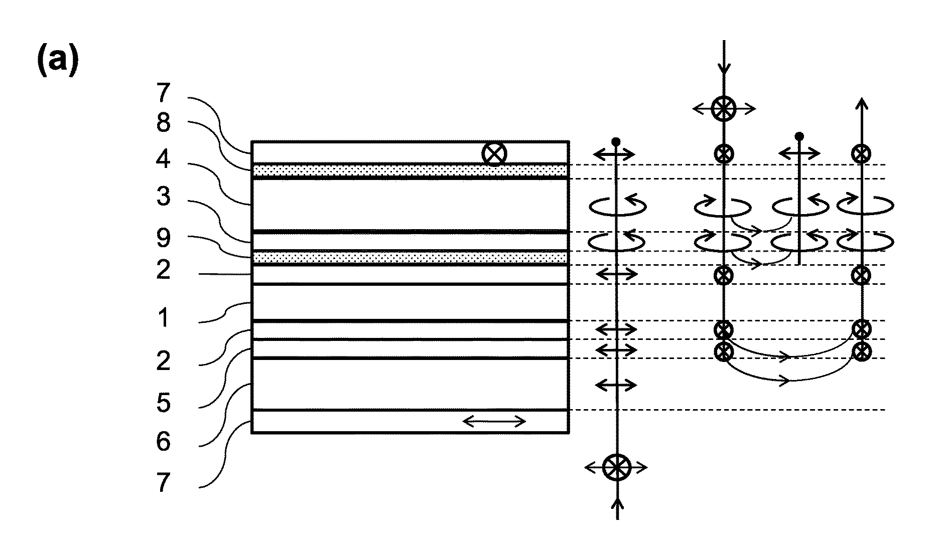
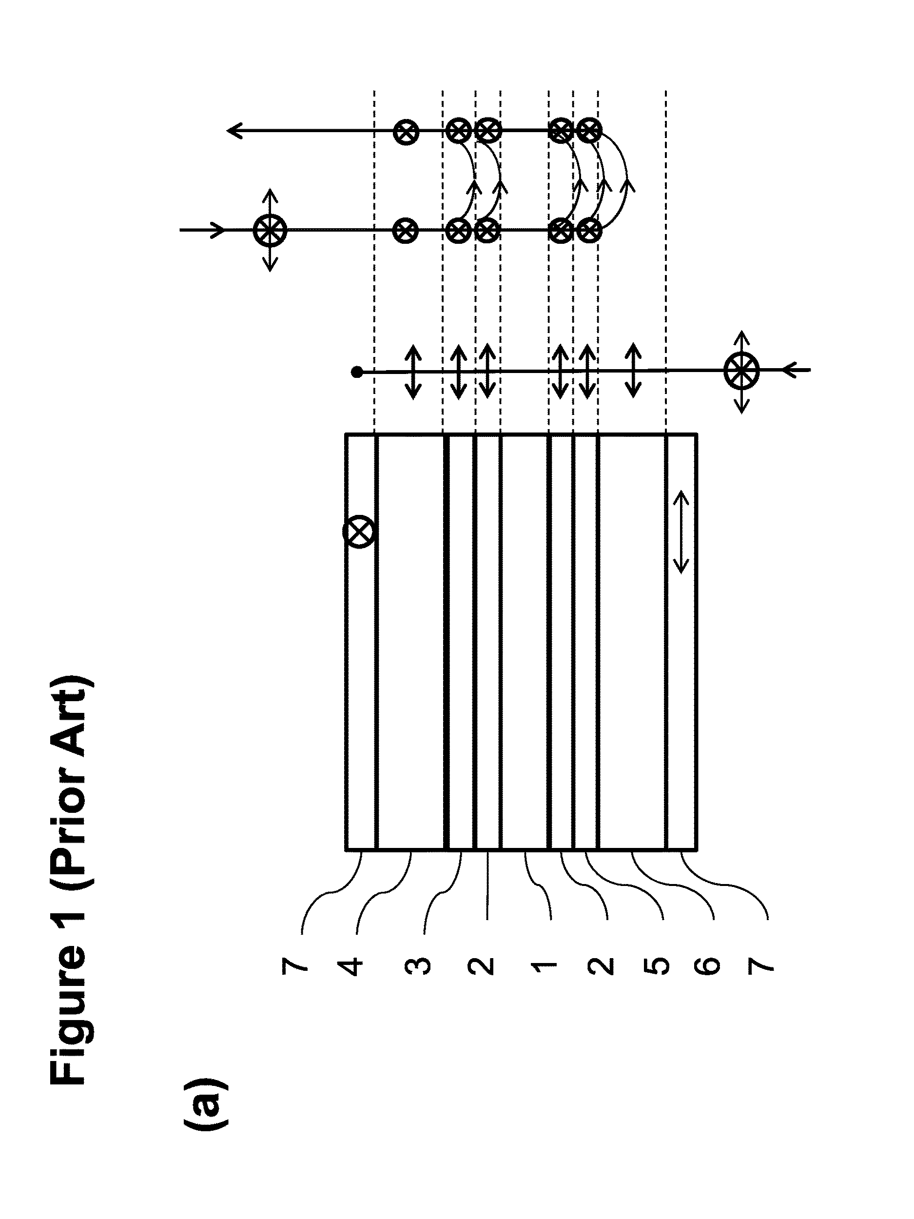
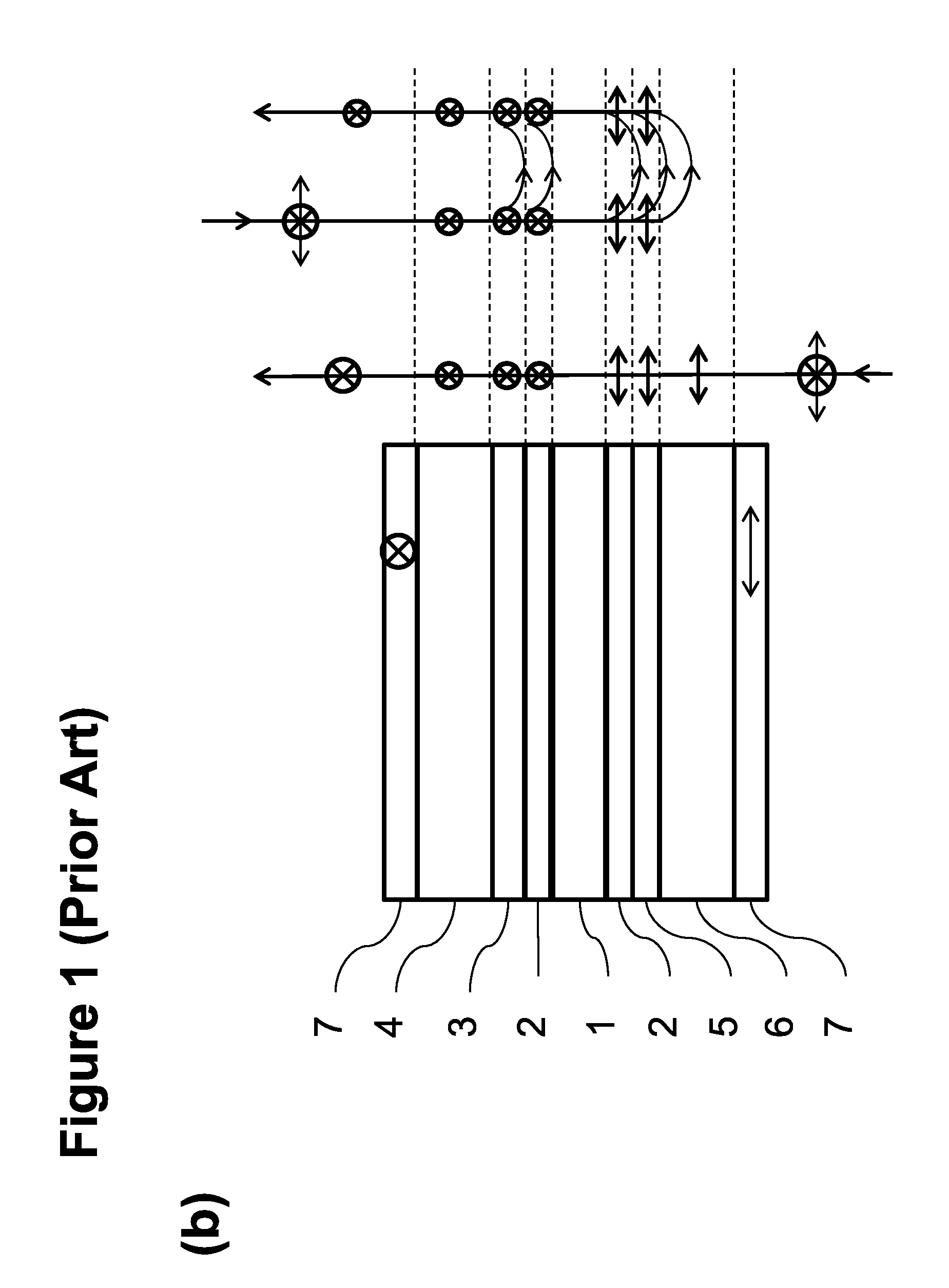
[0037]Referring to FIG. 1, a transmissive FFS type LCD of a known configuration which may be considered standard in the art, typically comprises an optical stack configuration in which the liquid crystal (LC) material (1) is sandwiched between two glass substrates with a uniform cell gap of typically 3-5 μm, alignment layers (2) are disposed on the inner surfaces of each substrate adjacent to the LC material to promote a uniform, antiparallel planar alignment of the LC, a colour filter layer (3) is disposed on the inner surface of the top (viewer-side) substrate (4), an active-matrix pixel array and drive electronics (5) are disposed on the inner surface of the lower or bottom (e.g., backlight-side) substrate (6), which also sometimes is referred to as the TFT substrate, and linear polarisers (7), optionally including a number of uniaxial or biaxial retardation films, are laminated onto the outer surfaces of both substrates, resulting in the transmission of linearly polarised light ...


PUM


Abstract

A display device in which ambient light reflections, for example, from IPS or FFS type displays are reduced by a circular polariser (e.g., linear polariser combined with external quarter waveplate) to make the light circular polarized, as it traverses the multiple reflective layers between the polariser and LC layer, and then an internal quarter waveplate converts the light back to linear polarisation before it enters the LC, so the display can operate as normal, while the circular polariser absorbs unwanted reflections of ambient light from within the display.

Description

TECHNICAL FIELD[0001]The invention has application within the field of consumer electronic displays, particularly transmissive and transflective mobile displays which are intended for some outdoor use and other use in potentially high ambient illumination situations.BACKGROUND ART[0002]In recent years, the performance of transmissive or emissive type displays such as LCD and OLED has increased significantly in metrics such as resolution, colour gamut capability and brightness, and decreased in cost such that they now form the large majority of the electronic displays market for most applications, both static and mobile, indoor and outdoor use. This has resulted in the retreat of reflective and transflective display types into niche applications for very high ambient illumination, and long battery life requirement applications. Even applications which until very recently a reflective display technology was preferred, such as outdoor signage, e-readers and smart wristwatches, are now ...

Claims


Application Information

Patent Timeline
IPC IPC(8): G02F1/1335G02F1/13363G02F1/1368G02F1/1343
CPCG02F1/133528G02F1/134363G02F1/133514G02F1/13363G02F2001/133638G02F1/133555G02F2001/134372G02F2001/133541G02F1/1368G02F2413/02G02F2413/04G02F2413/06G02F1/133638G02F1/133541G02F1/134372
Inventor SMITH, NATHAN JAMESHOPKIN, HYWELMINOURA, KIYOSHISAKAI, AKIRABROUGHTON, BENJAMIN JOHN
Owner SHARP KK
Why Eureka
Try Eureka