
Light emitting diode (LED) backlighting source

a technology of led light and backlighting source, which is applied in the field of led backlighting source, can solve the problems of high cost, high manufacturing cost, and inability to mount a plurality of such lights, and achieve the effect of increasing the constant illumination over the footprint, easy manufacturing, and high cos

Inactive Publication Date: 2017-02-02
MICHAELIDIS SPIROS
View PDF2 Cites 5 Cited by
  • Summary
  • Abstract
  • Description
  • Claims
  • Application Information

AI Technical Summary

Benefits of technology

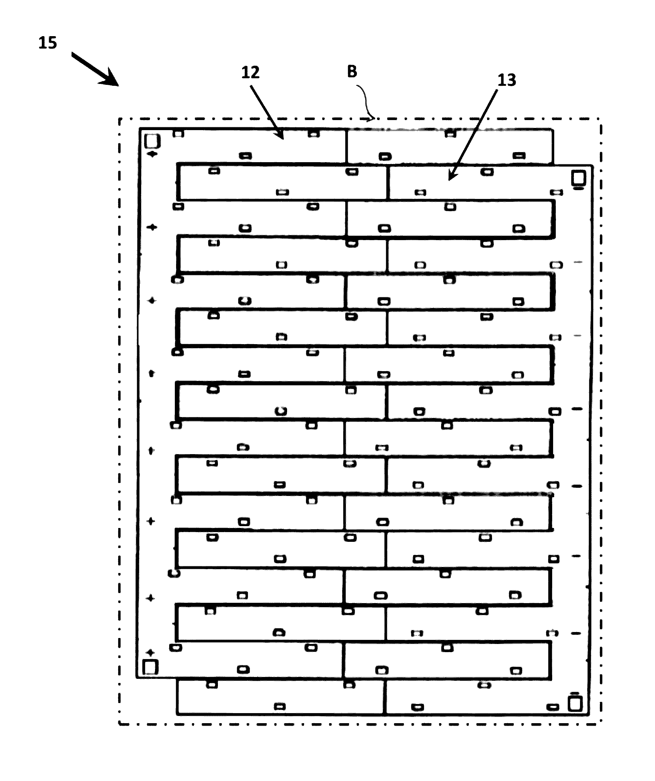
The invention offers a cost-effective way to create circuit boards for LED backlighting sources due to less material requirements. The finger portions allow for flexibility in the circuit board, which helps in accommodating temperature fluctuations and prevents warping or fracturing. The at least two circuit boards can be easily connected to form a large, flexible backlighting circuit board. In its simplest form, the invention allows for the creation of multiple display arrays with different footprints by connecting the circuit boards in a second configuration.

Problems solved by technology

Generally due to the bulkiness of such lights it is not practical to mount a plurality of such lights in order to give a substantially even spread of light.
A problem with these fluorescent and neon lights are that they are costly to manufacture and they are costly to run and can be quite readily damaged.
Further the fluorescent or neon material can readily expire in a relatively short period.
However clearly the use of LEDs has resulted in a return to the problem of light point sources and further problems occur due to the electronic nature of LEDs rather than usual electrical considerations of prior devices, In particular there is the problem of use of circuit boards to provide an array of LEDs.
This is restrictive in size and arrangement and costly in manufacture.
Further problems occur when using LEDs in light boxes as limitation of arrangement of the LEDs causes inconsistent illumination of a backlit substrate.
Consequently, when such an LED light box is used in advertising, in general illumination or in decorative light sources then unwanted light interference patterns or light dispersion patterns occur which affects the intended single light box illumination effect that was wanted.
Apart from aesthetic limitation there is also practical limitation as an inconsistent light source either provides a restricted general illumination from the backlighting of the translucent or semitranslucent substrate or provides a difficult to read backlit translucent or semitranslucent substrate that could include advertising material, or other information.

Method used


Image

  • Light emitting diode (LED) backlighting source
  • Light emitting diode (LED) backlighting source
  • Light emitting diode (LED) backlighting source

Examples


Embodiment Construction

[0056]It should be noted in the following description that like or the same reference numerals in different embodiments denote the same or similar features.

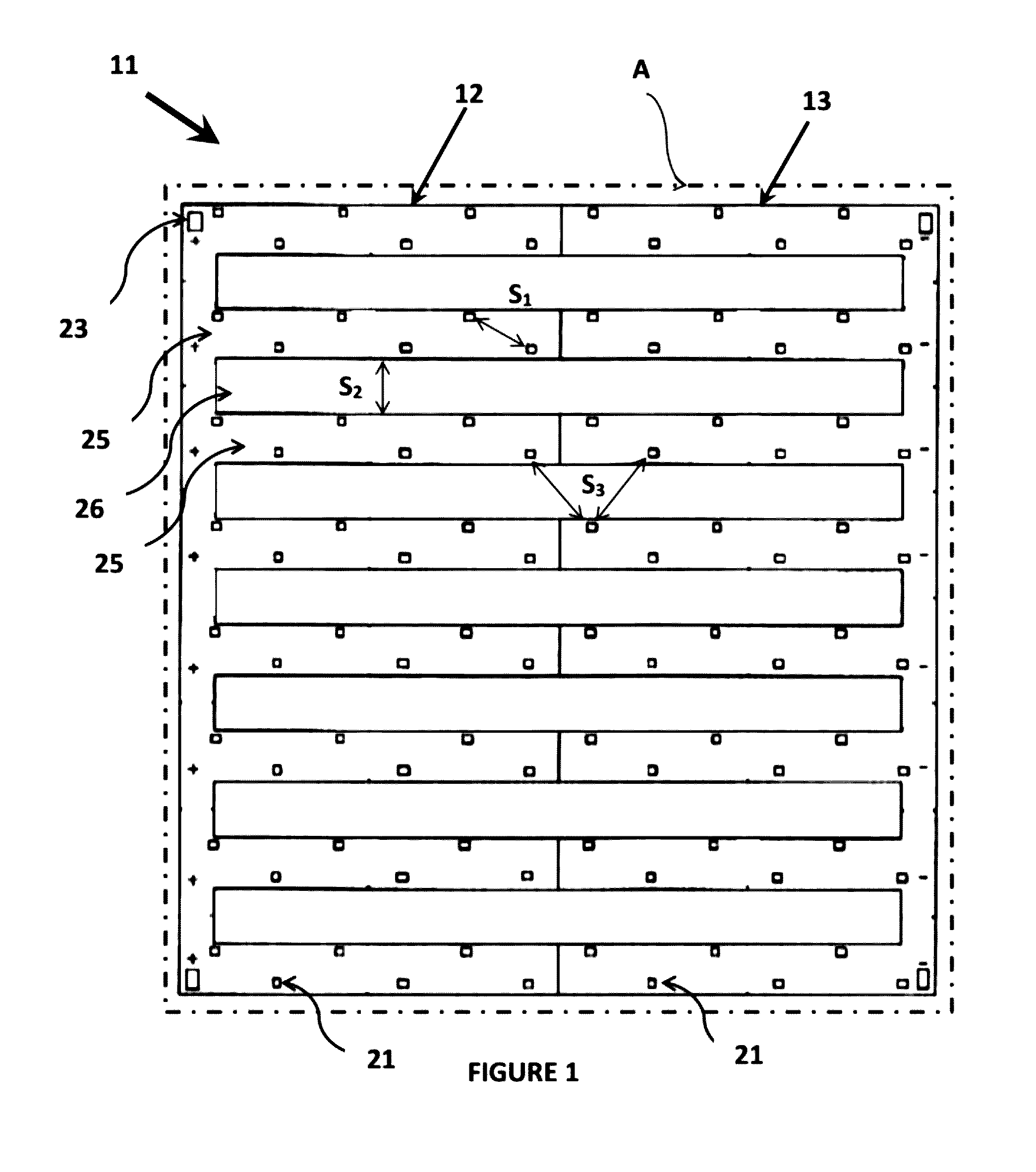
[0057]Referring to the drawings there is shown in FIG. 1 a light emitting diode (LED) backlighting source comprising at least one circuit board 11 electrically connectable to a power source (not shown) through connectors 23 and a plurality of LEDs 21 electrically mounted on the circuit board 11 and able to be powered by the connected power source.

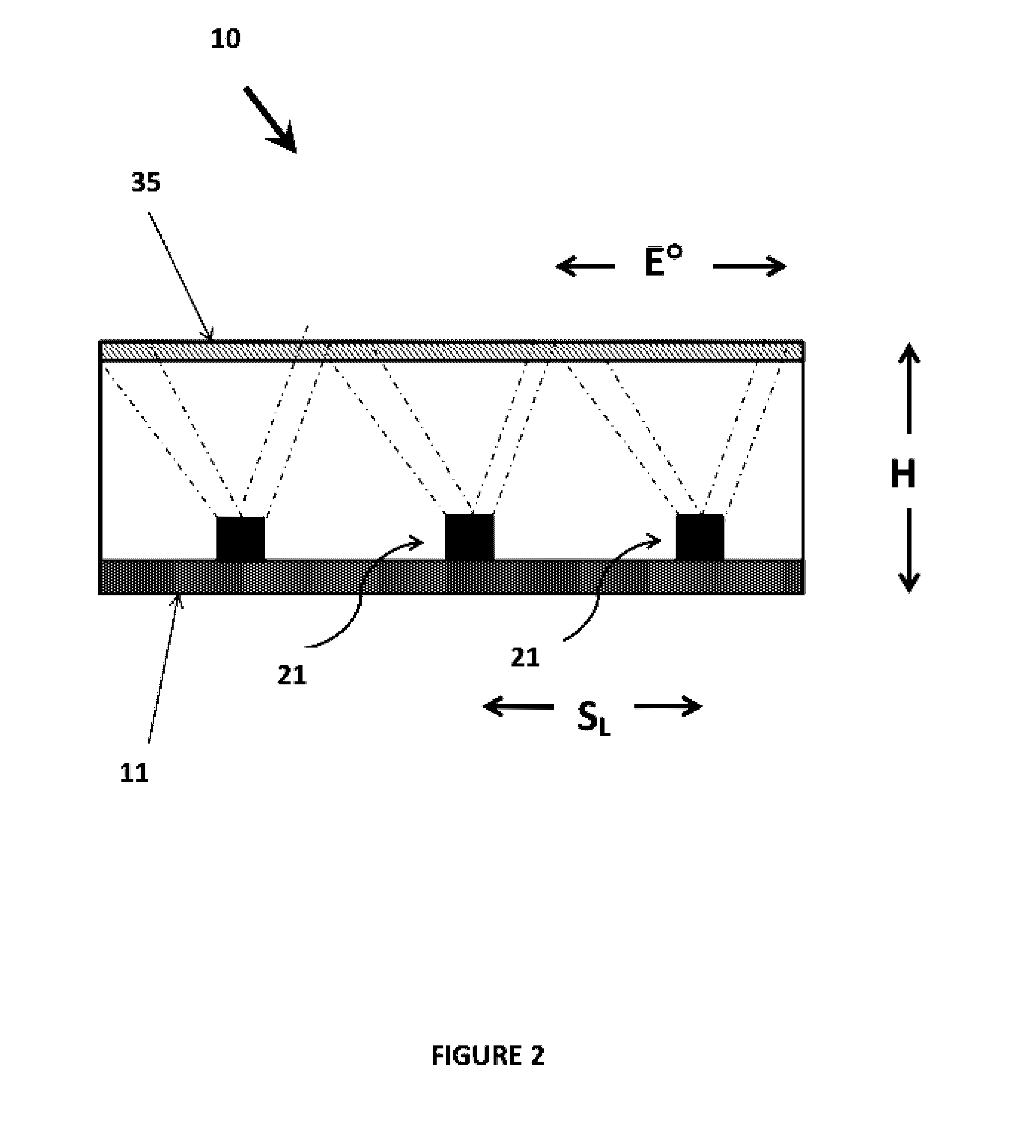
[0058]Referring to FIG. 2, there is shown an LED light source for backlighting a translucent or semitranslucent substrate 35 by way of spaced LEDs 21 on a circuit board 11 to provide a substantially uniform box light source 10 which can be used in advertising, in general illumination or in decorative light sources. The linear spacing SL and the limited angle E° provides a limiting height H that the translucent or semitranslucent substrate 35 needs to be away from the spaced LEDs 21 to pr...


PUM


Abstract

A light emitting diode (LED) backlighting source comprising at least one circuit board electrically connectable to a power source; a plurality of LEDs electrically mounted on the circuit board and able to be powered by a connected power source; wherein the circuit board is formed of a plurality of spaced finger portions and connecting portions wherein the finger portions and the connecting portions are electrically connected.

Description

TECHNICAL FIELD[0001]The present invention relates to a light emitting diode (LED) backlighting source.[0002]More particularly, the present invention relates to a modular structure of an LED light source for backlighting a translucent or semitranslucent substrate to provide a substantially uniform box light source. This can be used in advertising, in general illumination or in decorative light sources but is not so limited.PRIOR ART[0003]Light sources are generally a point source such as provided by incandescent lights, argon lights and other light globe structures. This form of light therefore irradiates from a small linear filament source which produces a substantially point source of light, if a large area is required to be illuminated then multiple point sources are required or light dispersion techniques are required such as by use of configurations of reflectors or Fresnel lenses or the like. Generally due to the bulkiness of such lights it is not practical to mount a pluralit...

Claims


Application Information

Patent Timeline
Patent Type & Authority Applications(United States)
IPC IPC(8): G09F13/04F21V19/00
CPCG09F13/04F21Y2105/003F21Y2101/02F21V19/003G09F13/0409G09F13/0413F21Y2105/16F21Y2115/10F21Y2105/12
Inventor MICHAELIDIS, SPIROS
Owner MICHAELIDIS SPIROS
Learn More