Devices, systems and methods for use in bone tissue

Inactive Publication Date: 2017-02-09
WOVEN ORTHOPEDIC TECH
View PDF2 Cites 7 Cited by
  • Summary
  • Abstract
  • Description
  • Claims
  • Application Information

AI Technical Summary

Benefits of technology

[0009]There is a need for devices, systems and methods that enhance the surface of a bone hole to provide enhanced fixation of a bone anchor to the bone. Additionally, there is a need for devices, systems and methods for repairing the surface of the bone hole following damage to the bone hole as in the case of stripping of the hole in the bone when a bone screw is over-tightened. Also, there is a need for devices, systems and methods for providing an enhanced bone hole surface for the reattachment of tendons in, for example anterior/posterior cruciate

Problems solved by technology

One complication with the use of bone screws is the loss of fixation or grip between the bone screw and the patient's bone.
Another complication with the use of bone screws is the stripping of the hole in the bone when the bone screw is inserted.
This results in the loss of purchase and holding strength of the bone screw.
The presence of osteoporotic bone can increase the likelihood of complications by reduci

Method used


Image

  • Devices, systems and methods for use in bone tissue
  • Devices, systems and methods for use in bone tissue
  • Devices, systems and methods for use in bone tissue

Examples


Embodiment Construction

[0040]Some embodiments of the current invention are discussed in detail below. In describing embodiments, specific terminology is employed for the sake of clarity. However, the invention is not intended to be limited to the specific terminology so selected. A person skilled in the relevant art will recognize that other equivalent components can be employed and other methods developed without departing from the broad concepts of the current invention. All references cited anywhere in this specification, including the Background and Detailed Description sections, are incorporated by reference as if each had been individually incorporated.

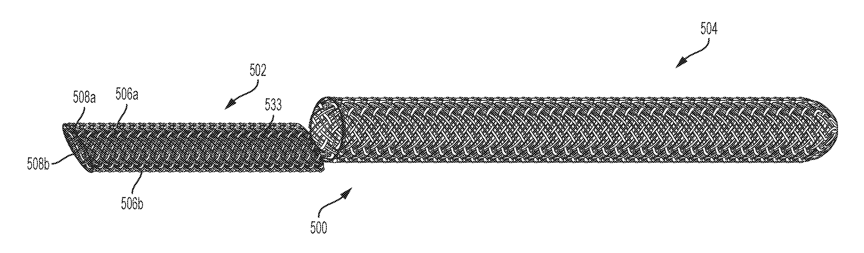
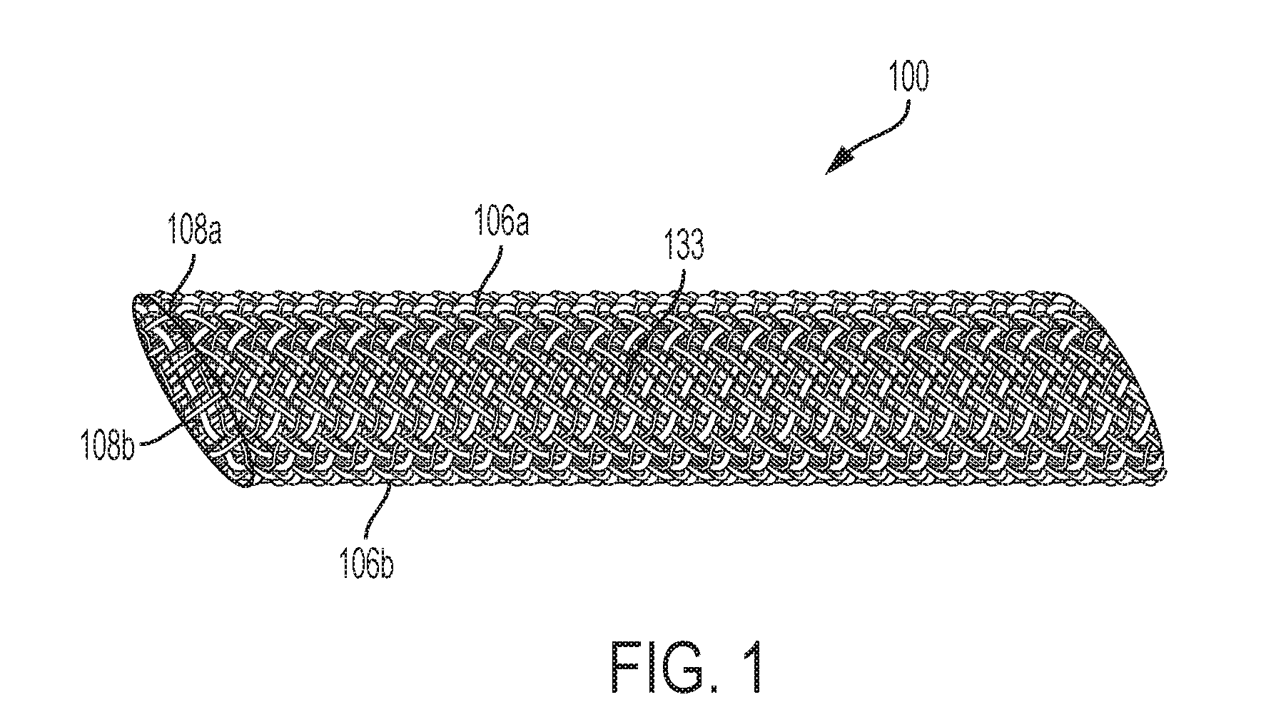
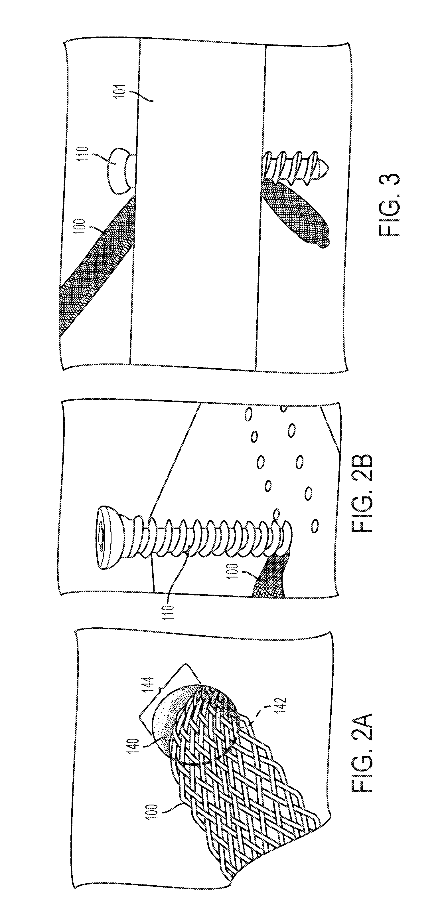
[0041]According to an embodiment of the present invention, a woven retention device can be inserted into a pilot hole and a screw can be inserted to abut the woven retention device. In this embodiment, a face of the screw makes contact with a flattened or folded-over woven retention device while a face of the screw makes contact directly with the bone...


PUM


Abstract

A woven retention device can include a pair of connected opposing lattice segments comprising intersecting filaments. The pair of connected opposing lattice segments can be configured to be placed in a portion of a circumference of a bone hole of a bone. A method of inserting a woven retention device can include inserting a woven retention device into a bone hole of a bone. The inserting the pair of opposing lattice segments can cover only a portion of a circumferential area of the bone hole. The method can include securing a fastening device into the bone hole having the inserted woven retention device. Upon securing the fastening device into the bone hole, a portion of the fastening device interfaces directly with the surface of the bone in the bone hole and a portion of the fastening device can interface directly with the bone interface of the woven retention device.

Description

CROSS-REFERENCE TO RELATED APPLICATIONS[0001]This application claims priority to U.S. Provisional Patent Application No. 62 / 201,314, filed Aug. 5, 2015, which is hereby incorporated by reference herein in its entirety.TECHNICAL FIELD[0002]The present invention relates to devices, systems and methods for use in fixing fasteners to bone tissue.BACKGROUND[0003]In orthopedic surgery it is common to secure a bone screw to a patient's bone. Bone fracture repair is surgery to fix a broken bone using plates, nails, screws, or pins. It is common in the treatment of fractures to attach a plate to the bone utilizing bone screws. The resulting construct prevents motion of the fractured bone so that the bone can heal. Alternatively, one or more screws may be inserted across the break to hold it in place.[0004]In the treatment of spinal disorders, pedicle screws are inserted into the patient's vertebrae to serve as anchor points that can then be connected with a rod. This construct prevents motio...

Claims


Application Information

Patent Timeline
IPC IPC(8): A61B17/84A61B17/88A61B17/86
CPCA61B17/842A61B2017/00853A61B17/88A61B17/86A61B17/686
Inventor MAGEE, FRANCIS PATRICKLUZZI, ROBERT
Owner WOVEN ORTHOPEDIC TECH
Why Eureka
Try Eureka