Modular heat exchange tower and method of assembling same

a technology of module heat exchange tower and heat exchange tower, which is applied in the direction of trickle cooler, transportation and packaging, light and heating apparatus, etc., can solve the problems of high labor intensity of towers, and high labor intensity of workers on the job si

Active Publication Date: 2017-02-09
SPX COOLING TECH
View PDF15 Cites 11 Cited by
  • Summary
  • Abstract
  • Description
  • Claims
  • Application Information

AI Technical Summary

Problems solved by technology

A drawback associated with current cooling towers is that in some applications they can be very labor intensive in their assembly at the job site.
The assembly of such towers oftentimes requires a dedicated labor force investing a large amount of hours.
Accordingly, such assembly is labor intensive requiring a large amount of time and therefore can be costly.
Uncertainties such as weather and site conditions may also affect the time required to assemble cooling towers at a job site.
The quality of the labor force may also lead to quality and performance issues associated with the towers.
But while it may be desirable to assemble tower components at a factory, conventional designs for cooling towers oftentimes necessitate their assembly at a job site.
For example, factors such as the size of the various tower components and their structural strength may limit their ability to be manufactured at the factory and transported onsite.
One particular component that may present assembly and transportation challenges is the liquid collection basin or commonly referred to as the cold water basin.
Due to the size of the cold water basin, it is costly to transport it in pre-assembled form to a job site.
While a solution may be to ship the cold water basin in multiple components to a job site for final assembly, such leads to greater labor costs and inconsistent quality in assembly due to on-site conditions such as those described above.
Moreover, it oftentimes is difficult to ensure that the various components of the cold water basin are fully sealed to one another at a job site.

Method used


Image

  • Modular heat exchange tower and method of assembling same
  • Modular heat exchange tower and method of assembling same
  • Modular heat exchange tower and method of assembling same

Examples


Embodiment Construction

[0023]In the following detailed description, reference is made to the accompanying drawings, which form a part hereof and show by way of illustration specific embodiments in which the invention may be practiced. These embodiments are described in sufficient detail to enable those skilled in the art to practice them, and it is to be understood that other embodiments may be utilized, and that structural, logical, processing, and electrical changes may be made. It should be appreciated that any list of materials or arrangements of elements is for example purposes only and is by no means intended to be exhaustive. The progression of processing steps described is an example; however, the sequence of steps is not limited to that set forth herein and may be changed as is known in the art, with the exception of steps necessarily occurring in a certain order.

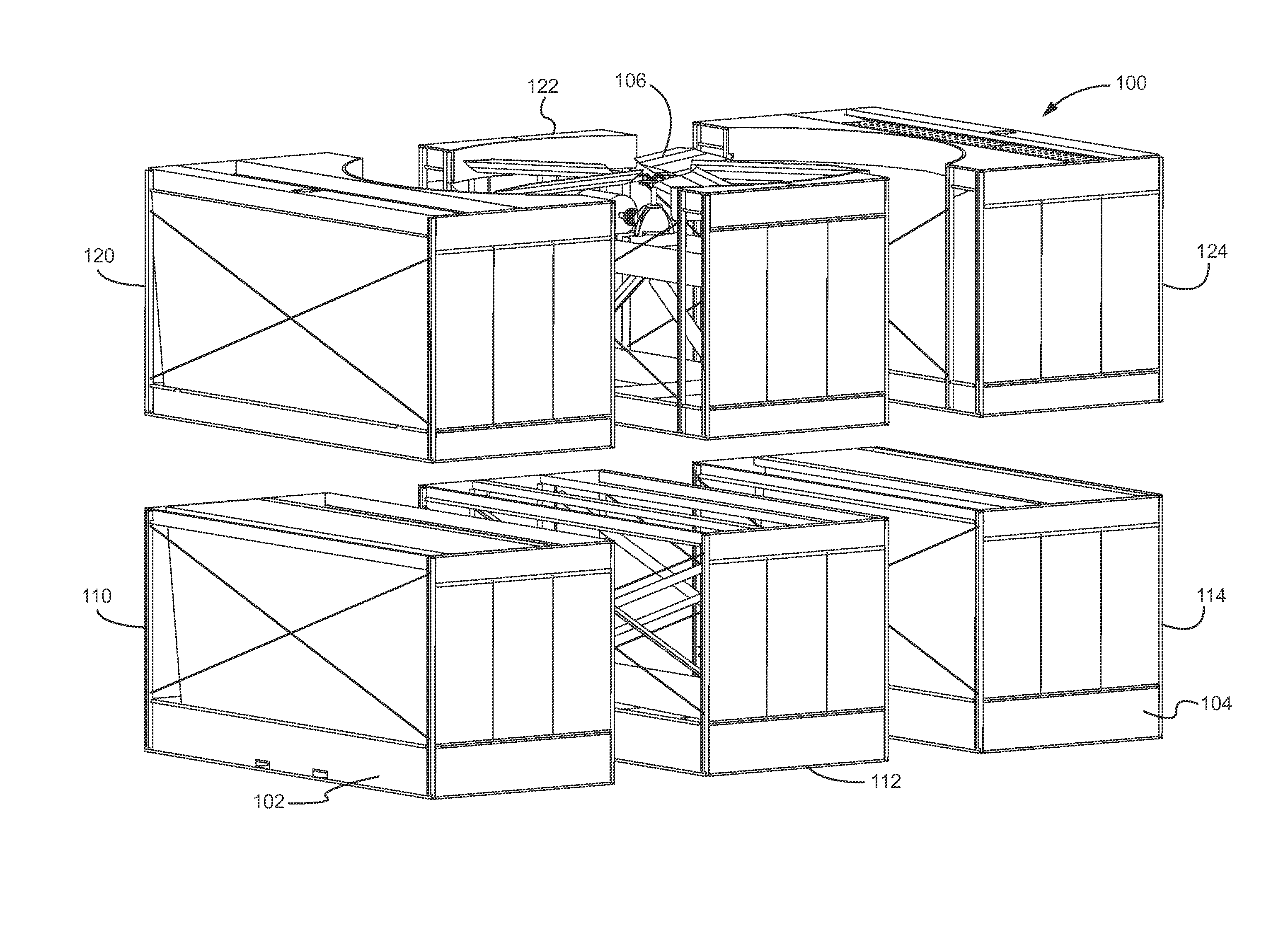
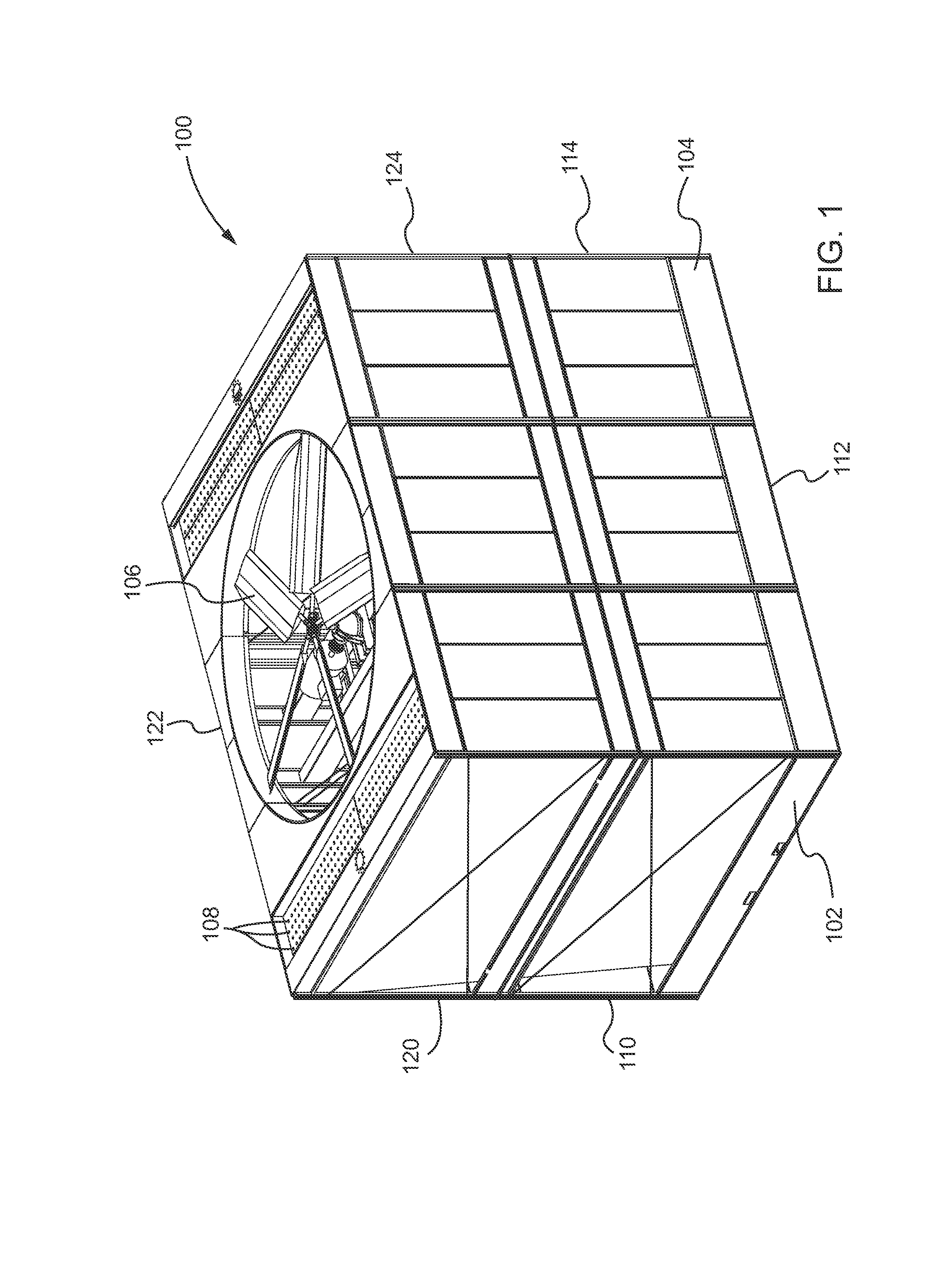
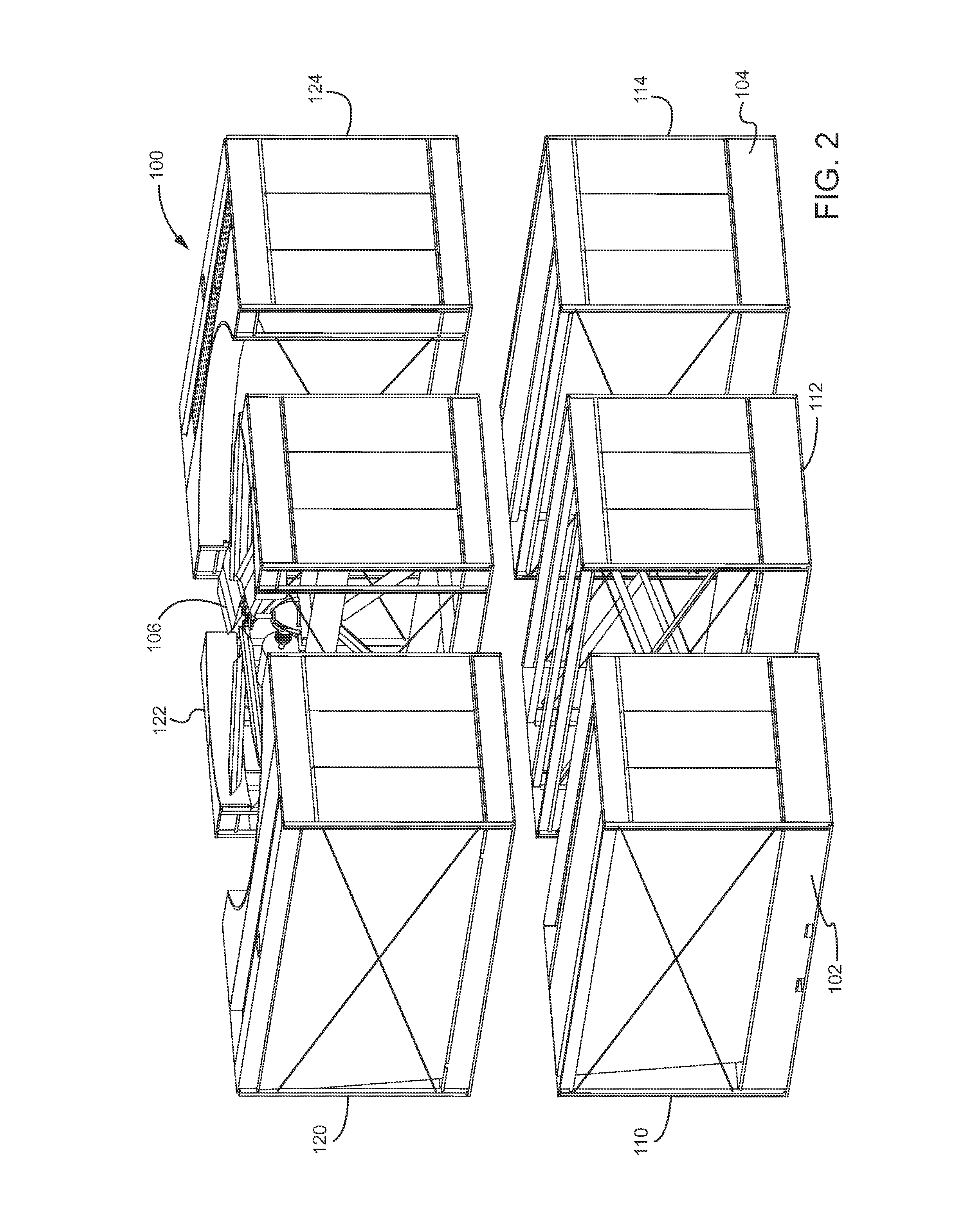
[0024]Cooling towers regulate the temperature of relatively warm or hot fluid by passing the fluid through a tower apparatus that bring...


PUM

PropertyMeasurementUnit
widthaaaaaaaaaa
widthaaaaaaaaaa
widthaaaaaaaaaa

Abstract

The present disclosure relates to a modular heat exchange tower comprising a first module comprising a first basin disposed therein and a second module comprising a second basin disposed therein. The aforementioned modular heat exchange tower may also include heat exchange sections, which are disposed in the first module and the second module. The first module and the second module may be assembled prior to being transported to a job site and installed in the modular heat exchange tower.

Description

FIELD OF THE INVENTION[0001]The present disclosure relates generally to modular heat exchange towers. The present disclosure also relates to methods of assembling modular heat exchange towers. More particularly, the present disclosure relates, for example, to modular components of heat exchange towers, each having separate water basins disposed therein, that can be pre-assembled in a factory setting and transported to a job site and assembled to erect a cooling tower.BACKGROUND OF THE INVENTION[0002]Cooling towers are heat exchangers of a type widely used to emanate low grade heat into the atmosphere and are typically utilized in electricity generation, air conditioning installations, and the like. These towers receive a relatively warm or hot fluid, and pass the fluid through the tower apparatus so that heat is extracted from the fluid by interaction with relatively cooler ambient air.[0003]Cooling towers generally include counter-flow type cooling towers and cross-flow type coolin...

Claims


Application Information

Patent Timeline
Patent Type & Authority Applications(United States)
IPC IPC(8): E04H5/12B23P15/26B01F3/04
CPCE04H5/12B23P15/26B01F3/04F28C1/00F28F25/02F28C1/04F28F2025/005F28F25/04B01F23/20F28C1/14E04B1/34861
Inventor MAURER, SCOTTHINK, PAUL
Owner SPX COOLING TECH
Why Eureka
Try Eureka