Ingress protection for reducing particle infiltration into acoustic chamber of a MEMS microphone package

a technology of ingress protection and acoustic chamber, which is applied in the field of mems microphones, can solve the problem that patents do not disclose ingress protection, and achieve the effect of improving the protection of the enclosed mems microphon

Active Publication Date: 2017-02-09
KNOWLES ELECTRONICS INC
View PDF4 Cites 41 Cited by
  • Summary
  • Abstract
  • Description
  • Claims
  • Application Information

AI Technical Summary

Benefits of technology

[0004]The disclosed invention is directed to a MEMS microphone comprising a surface-mount package that encloses a MEMS microphone die, allows acoustic energy to impinge upon the enclosed MEMS microphone die, provides an electrical interface for the enclosed MEMS microphone die, provides the pressure reference for proper operation of the enclosed MEMS microphone die, and protects the enclosed MEMS microphone die from light, electromagnetic interference, environmental contaminants, and physical damage. The disclosed invention improves the protection for the enclosed MEMS microphone die from environmental contaminants by disposing a flange or an extension in the acoustic port of the cover of the MEMS microphone, the flange or the extension configured to limit the entry of environmental contaminants into the acoustic chamber where the MEMS microphone die is disposed.
[0006]The embodiments of the disclosed invention incorporate many features of the conventional MEMS microphone disclosed above, and further incorporate the use of ingress protection on the acoustic port in the cover to limit the entry of potential environmental contaminants into the acoustic chamber of the MEMS microphone, thereby protecting the MEMS microphone die disposed in the acoustic chamber. In some embodiments of the disclosed invention, the ingress protection is a formed member that is part of the acoustic port. The formed member can be configured into various shapes that provide access into the acoustic chamber for acoustic energy impinging upon the MEMS microphone, and is contiguous with the cover material. In other embodiments, the ingress protection is a stand-off shield that is mounted on the inner surface of the cover. The stand-off shield can be configured with multiple ports, open ends, or combinations of both. The stand-off shield can comprise a metal or plastic or composite material, and is attached to the cover with adhesive, solder, or other attachment methods. In other embodiments, the ingress protection is a stand-off shield that is mounted on the inner surface of the cover combined with a formed member as described earlier. In other embodiments, the ingress protection is a shallow cavity formed in the exterior surface of the cover, with the acoustic port for the MEMS microphone disposed within the shallow cavity. A shield member is disposed with the cavity and covers the acoustic port, but allows acoustic pressure to enter the acoustic port while limiting the entry of environmental contaminants. In other embodiments, the ingress protection is a shallow cavity formed in the exterior surface of the cover, with the acoustic port for the MEMS microphone disposed within the shallow cavity. A shield member is disposed with the cavity and covers the acoustic port, but allows acoustic pressure to enter the acoustic port while limiting the entry of environmental contaminants. In other embodiments, a formed member is mechanically attached with solder or other adhesives to the inner surface of the cover immediately adjacent to the acoustic port in the cover.

Problems solved by technology

Although the Knowles patents disclose the use of an environmental barrier in the acoustic port in the cover of a MEMS microphone, such as a polymer material or sintered metal, the Knowles patents do not disclose ingress protection comprising a formed member, an internal shield, a combination of the formed member and the internal shield, or a shallow cavity formed in an external surface of the cover of the MEMS microphone and having a shield member disposed therein.

Method used


Image

  • Ingress protection for reducing particle infiltration into acoustic chamber of a MEMS microphone package
  • Ingress protection for reducing particle infiltration into acoustic chamber of a MEMS microphone package
  • Ingress protection for reducing particle infiltration into acoustic chamber of a MEMS microphone package

Examples


Embodiment Construction

[0074]A detailed description of embodiments of the disclosed invention will now be given referring to the accompanying drawings.

[0075]While the disclosed invention is susceptible to embodiments in many different forms, there is shown in the drawings, and will herein be described in detail, preferred embodiments of the disclosed invention with the understanding that the present disclosure is to be considered as an exemplification of the principles of the disclosed invention and is not intended to limit the broad aspect of the disclosed invention to the embodiments illustrated.

Top-Port MEMS Microphone Embodiments

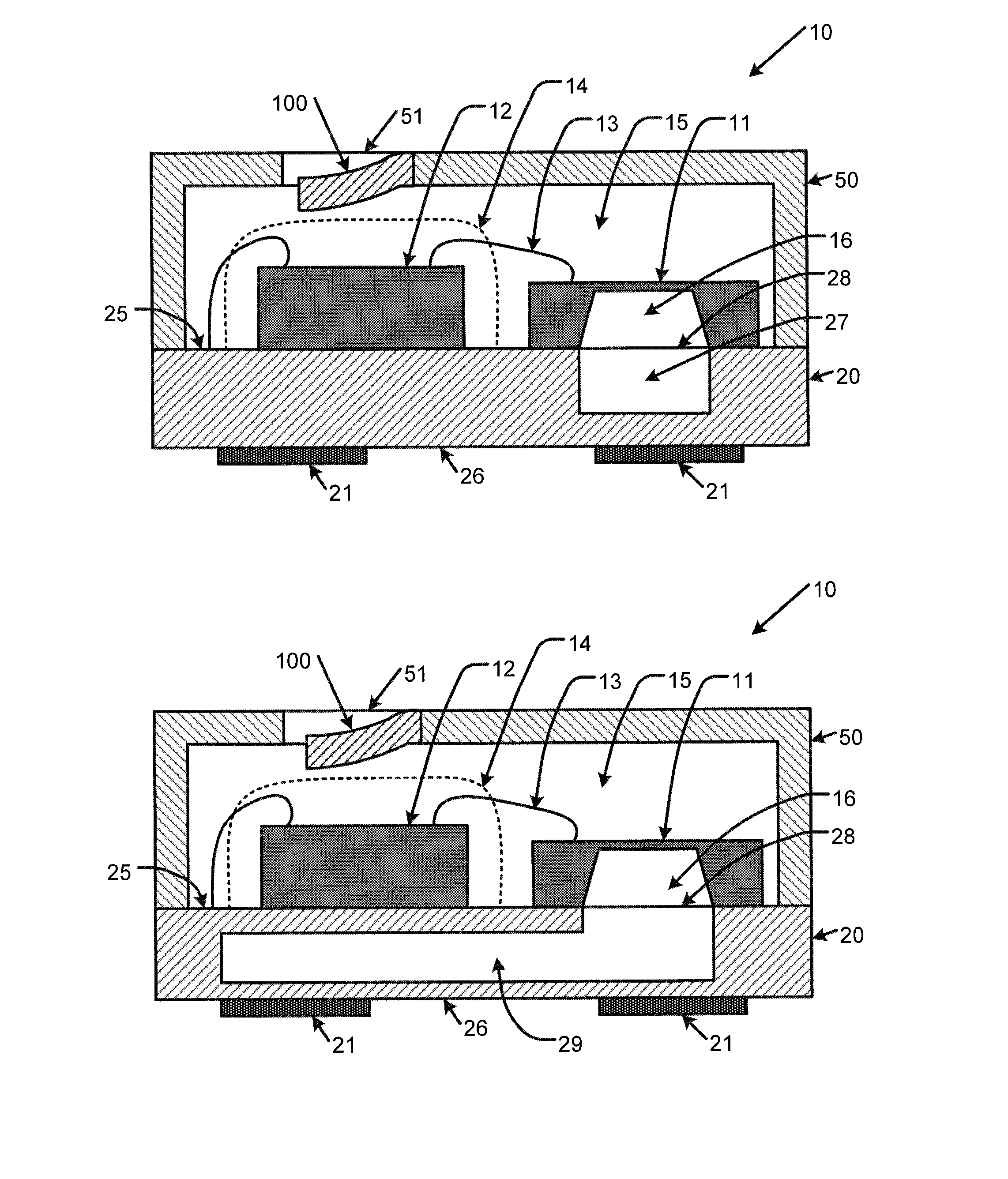
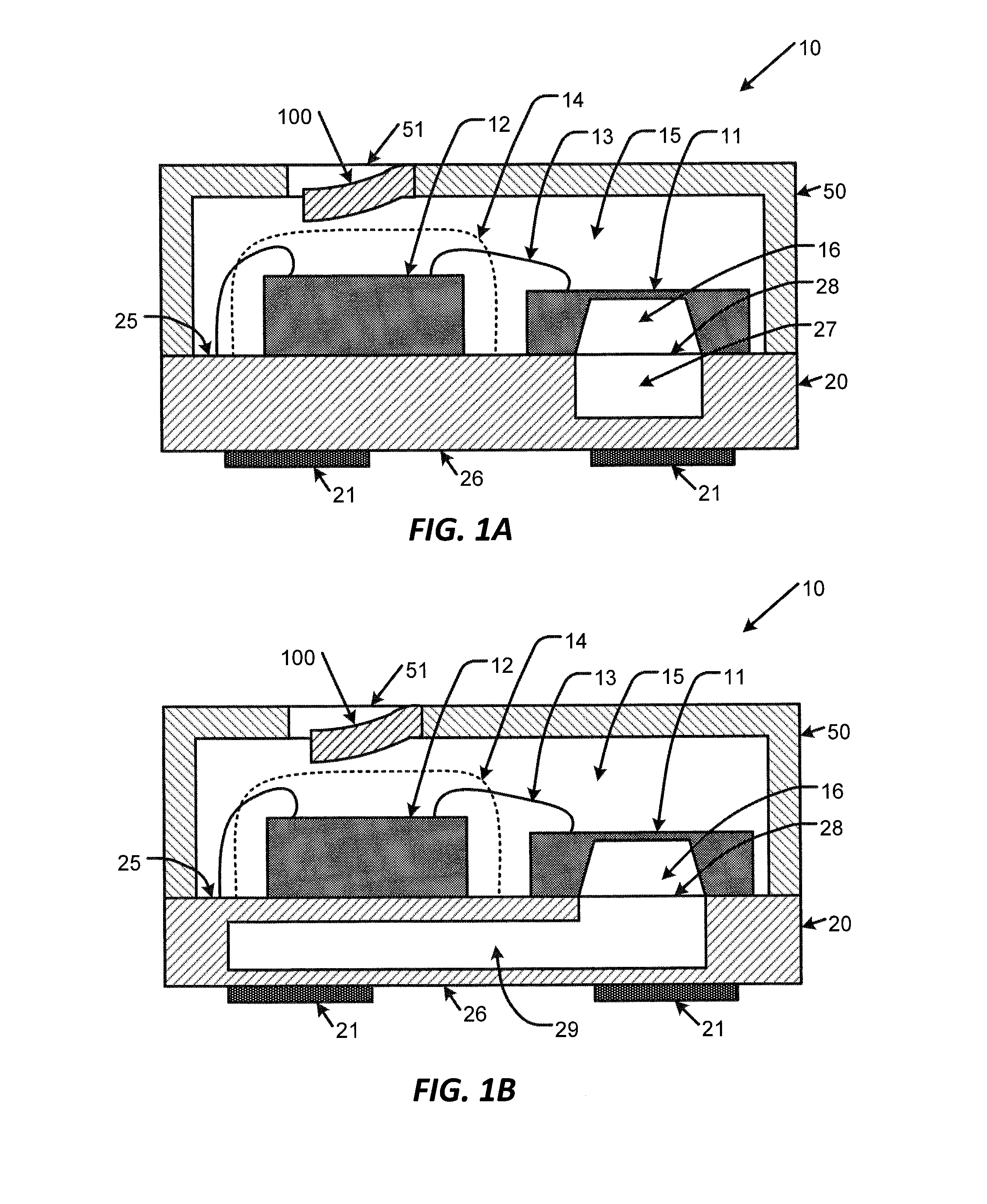
[0076]Now, referring to FIGS. 1A and 1B, several embodiments of a MEMS microphone 10 are illustrated. These particular embodiments are referred to as “top-port” MEMS microphones, since the cover 50 has an acoustic port 51 (also referred to an “aperture”). The MEMS microphone 10 preferably comprises a MEMS microphone die 11, e.g., as disclosed in U.S. Pat. Nos. 5,870,482 and 6,...


PUM


Abstract

A surface-mountable MEMS microphone comprising a MEMS microphone die and an application-specific integrated circuit (ASIC) mounted inside a surface-mountable package housing, and fully enclosed therein. The surface-mountable package is a single, self-contained housing that provides an electrical interface to external circuitry for the enclosed MEMS microphone die and the ASIC, and provides electrical, physical, and environmental protection for the MEMS microphone die and the ASIC. The surface-mountable package allows external acoustic energy to enter the package interior via one or more acoustic ports and impinge on the diaphragm of the MEMS microphone die. The cover of the surface-mountable package comprises an acoustic port with ingress protection to limit dust and particle intrusion. The ingress protection can be a formed member that is part of the cover of the surface-mountable package having various shapes, an internal shield, or a combination of both a formed member and internal shield.

Description

CROSS-REFERENCE TO RELATED APPLICATIONS[0001]There are no related applications.TECHNICAL FIELD OF THE DISCLOSED INVENTION[0002]The disclosed invention relates to a MEMS microphone comprising a surface-mountable package, a MEMS microphone die, and an application-specific integrated circuit (ASIC), wherein the MEMS microphone die and the ASIC are mounted inside the package housing, and fully enclosed therein. The surface-mountable package is a single, self-contained housing that provides an electrical interface to external circuitry for the enclosed MEMS microphone die and the ASIC, suppresses or reduces electromagnetic interference, provides environmental protection for the MEMS microphone die and the ASIC, and prevents external forces from damaging the MEMS microphone die and the ASIC. The surface-mountable package is configured for mechanical attachment to a land pattern on an end user printed circuit board, and for electrically coupling to electrical circuitry linked to the land p...

Claims


Application Information

Patent Timeline
Patent Type & Authority Applications(United States)
IPC IPC(8): H04R1/02H04R19/04H04R19/00
CPCH04R1/023H04R2201/003H04R19/04H04R19/005H04R17/00H04R17/02H01L2224/48137
Inventor WATSON, JOSHUAGROSSE, DANIEL TODDJACOBS, MICHAEL ROBERTSCHIMPF, WILLIAM F.DEL VALLE FIGUEROA, IVELISSE
Owner KNOWLES ELECTRONICS INC
Why Eureka
Try Eureka