Tracking sensor

a technology of tracking sensor and tracking battery, applied in the field of tracking sensors, can solve the problems of consuming battery, affecting the operation of the tracking device, and requiring substantial time and effort on the part of the owner to track a large number of cattle, and achieve the effect of not causing discomfort and light weigh

Active Publication Date: 2017-02-16
GARRITY POWER SERVICES
View PDF1 Cites 20 Cited by
  • Summary
  • Abstract
  • Description
  • Claims
  • Application Information

AI Technical Summary

Benefits of technology

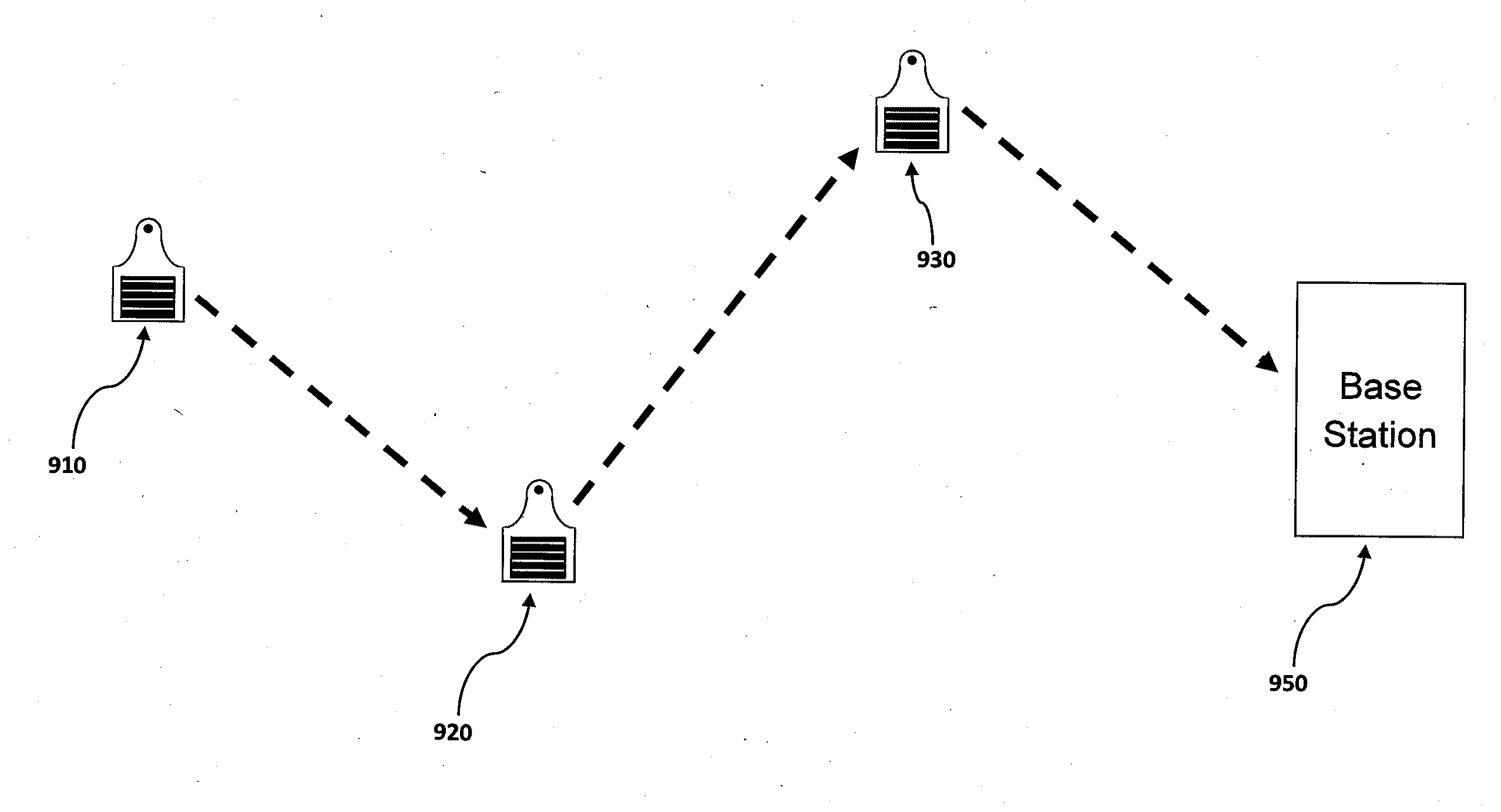
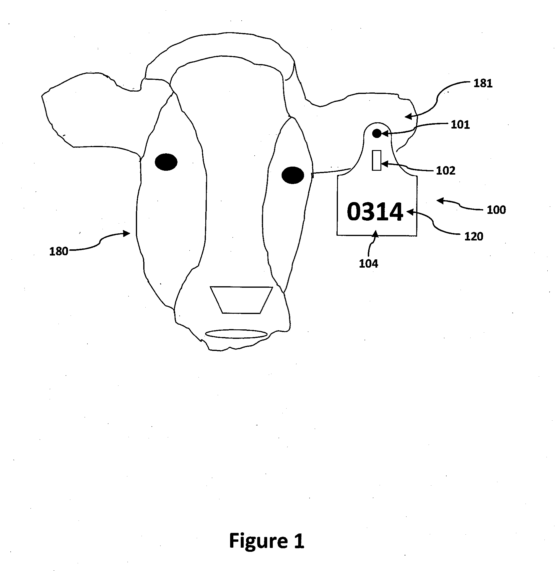
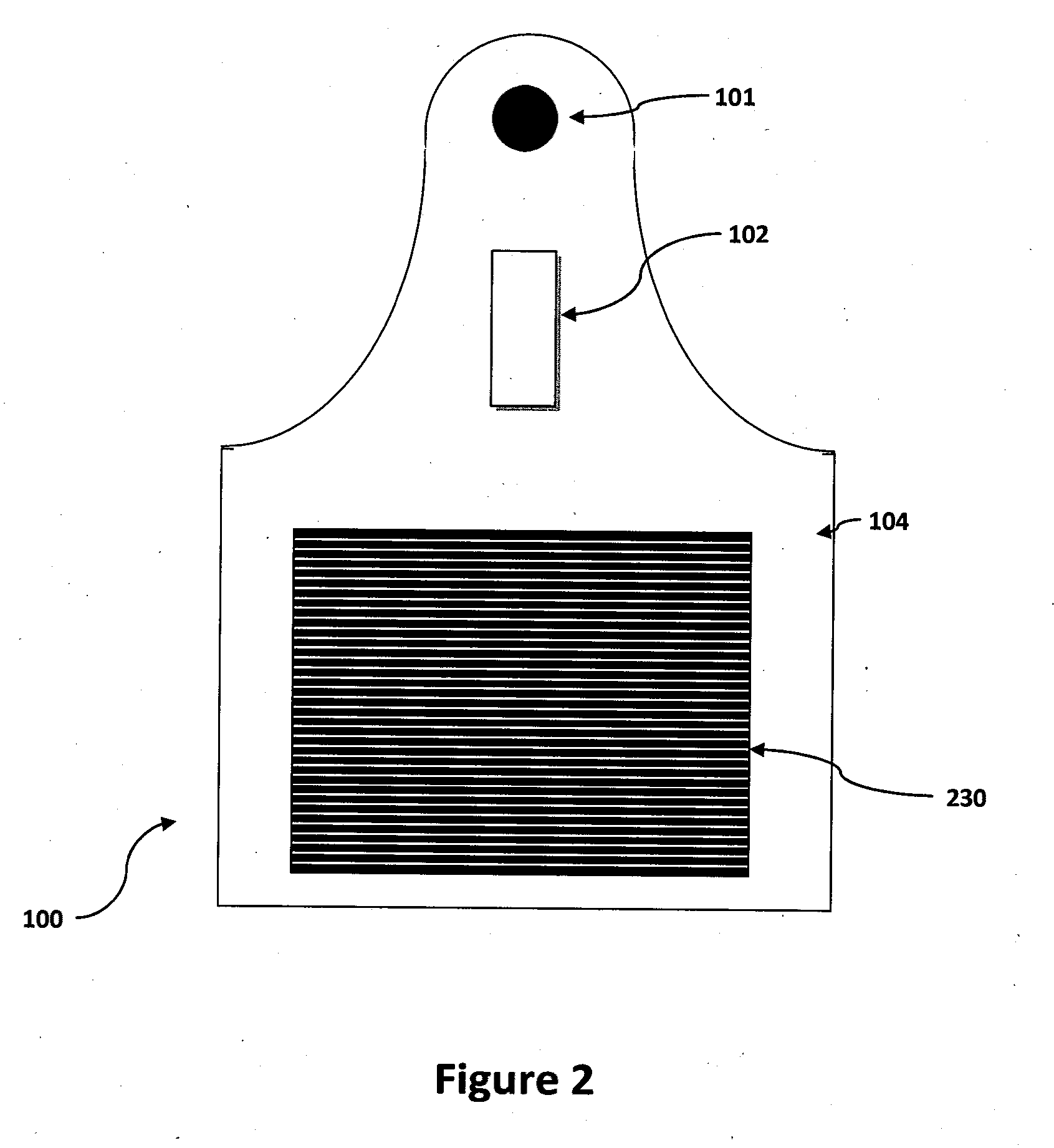
[0006]The present invention solves the above-described problems and provides a distinct advance in the art of cattle tracking. Specifically, the present invention includes a tracking tag, such as an ear tag for cattle, which comprises a renewable power source, a microcontroller, and a low-power long-range transmitter or transceiver than can transmit signals over long distance, and which draws nearly no quiescent current when it is not transmitting or receiving information. This tracking tag obviates the need for bringing a transmitter near the animal or getting all of the animals to come near a transmitter, due to its ability to transmit over very long distances. The tracking tag also allows an owner to track a large number of animals including knowing their position and obtaini

Problems solved by technology

Visual indicators require substantial time and effort on the part of owners to track large number of cattle.
Passive RFID tags are only powered when in close proximity to the transmitter (which occurs only a small fraction of each day), so these tags are unable to collect any information about the animal.
However, the drain on the battery presents problems with need to frequently re

Method used


Image

  • Tracking sensor
  • Tracking sensor
  • Tracking sensor

Examples


Embodiment Construction

[0020]The following detailed description of the invention references the accompanying drawings that illustrate specific embodiments in which the invention can be practiced. The embodiments are intended to describe aspects of the invention in sufficient detail to enable those skilled in the art to practice the invention. Other embodiments can be utilized and changes can be made without departing from the scope of the present invention. The following detailed description is, therefore, not to be taken in a limiting sense. The scope of the present invention is defined only by the appended claims, along with the full scope of equivalents to which such claims are entitled.

[0021]In this description, references to “one embodiment”, “an embodiment”, or “embodiments” mean that the feature or features being referred to are included in at least one embodiment of the technology. Separate references to “one embodiment”, “an embodiment”, or “embodiments” in this description do not necessarily ref...


PUM


Abstract

Tracking tags for attachment to an object or animal. The tracking tags may include low-power long-range transmitters drawing power from a battery or a renewable energy source. The tracking tags may also each include a microcontroller having a sleep-mode module enabling nearly no quiescent current to be drawn when the microcontroller is in a sleep-mode. The microcontroller may enter into a sleep-mode for long periods of time following a short period of sending data to the low-power long-range transmitter. The short period of sending data may be approximately one-twentieth of the long sleep-mode period. The tracking tags may also include sensors for determining an ambient temperature or biometric data about an animal to which the tracking tag is attached. Locations of the tracking tags may be determined using signal trilateration and/or signal triangulation.

Description

RELATED APPLICATIONS[0001]This patent application claims priority benefit to a provisional patent application titled “Cattle Tracking Sensor” U.S. Application No. 62 / 204,770, filed Aug. 13, 2015, incorporated by reference herein in its entirety.TECHNICAL FIELD[0002]The present invention is directed, in general, to tracking sensors and, more specifically, to an apparatus to provide a tracking sensor for cattle.BACKGROUND[0003]Cattle tracking has traditionally been done by tagging cattle with a visual indicator showing a number. This visual indicator was previously done by branding but is more commonly done now with ear tags. Visual indicators require substantial time and effort on the part of owners to track large number of cattle.[0004]In the past decade, passive Radio Frequency Identification (RFID) began to be used in tagging cattle. Passive RFID involves sending small amounts of energy and signals to a device in close proximity to the transmitter. The transmitted energy provides ...

Claims


Application Information

Patent Timeline
IPC IPC(8): A01K11/00G01S5/02G06K7/10
CPCA01K11/008G06K7/10366A01K11/004G01S5/0226G01S5/0294G06K19/0705G06K19/0723G06K19/07758G06K19/0711
Inventor GARRITY, PAUL
Owner GARRITY POWER SERVICES
Why Eureka
Try Eureka