Eureka AIR delivers breakthrough ideas for toughest innovation challenges, trusted by R&D personnel around the world.

Lighting device and luminaire

Active Publication Date: 2017-02-16
SIGNIFY HOLDING B V
View PDF2 Cites 1 Cited by
  • Summary
  • Abstract
  • Description
  • Claims
  • Application Information

AI Technical Summary

Benefits of technology

The invention is about a lighting device that uses SSL elements to achieve a more even distribution of light. This results in a more uniform, high-quality light.

Problems solved by technology

With a continuously growing population, it is becoming increasingly difficult to meet the world's energy needs and, simultaneously, to control carbon emissions to kerb greenhouse gas emissions which are considered responsible for global warming phenomena.
Indeed, in many jurisdictions the production and retailing of incandescent light bulbs has been outlawed, thus forcing consumers to buy energy-efficient alternatives, e.g. when replacing incandescent light bulbs.
Without such measures, the SSL-based lighting device may produce a spotty and / or more restricted luminous output.
However, this design has some notable drawbacks.
Firstly, due to the fact that the LEDs are enveloped by the end surface of the light guide body, the minimum thickness of light guide body must exceed the width of the LEDs.
Such a relatively thick light guide body may compromise the luminous efficiency of the lighting device.
Moreover, thermal management of the LEDs may become an issue if a relatively large number of LEDs has to be provided on the printed circuit board, for instance to produce a retrofit light bulb having a luminous output equivalent to a 75 W or 100 W incandescent light bulb, due to the intimate coupling between the light guide body and the LEDs.
Finally, due to the fact that the light guide body terminates on the printed circuit board, this lighting arrangement is incapable of generating a luminous distribution closely resembling that of an incandescent light bulb.

Method used


Image

  • Lighting device and luminaire
  • Lighting device and luminaire
  • Lighting device and luminaire

Examples


Embodiment Construction

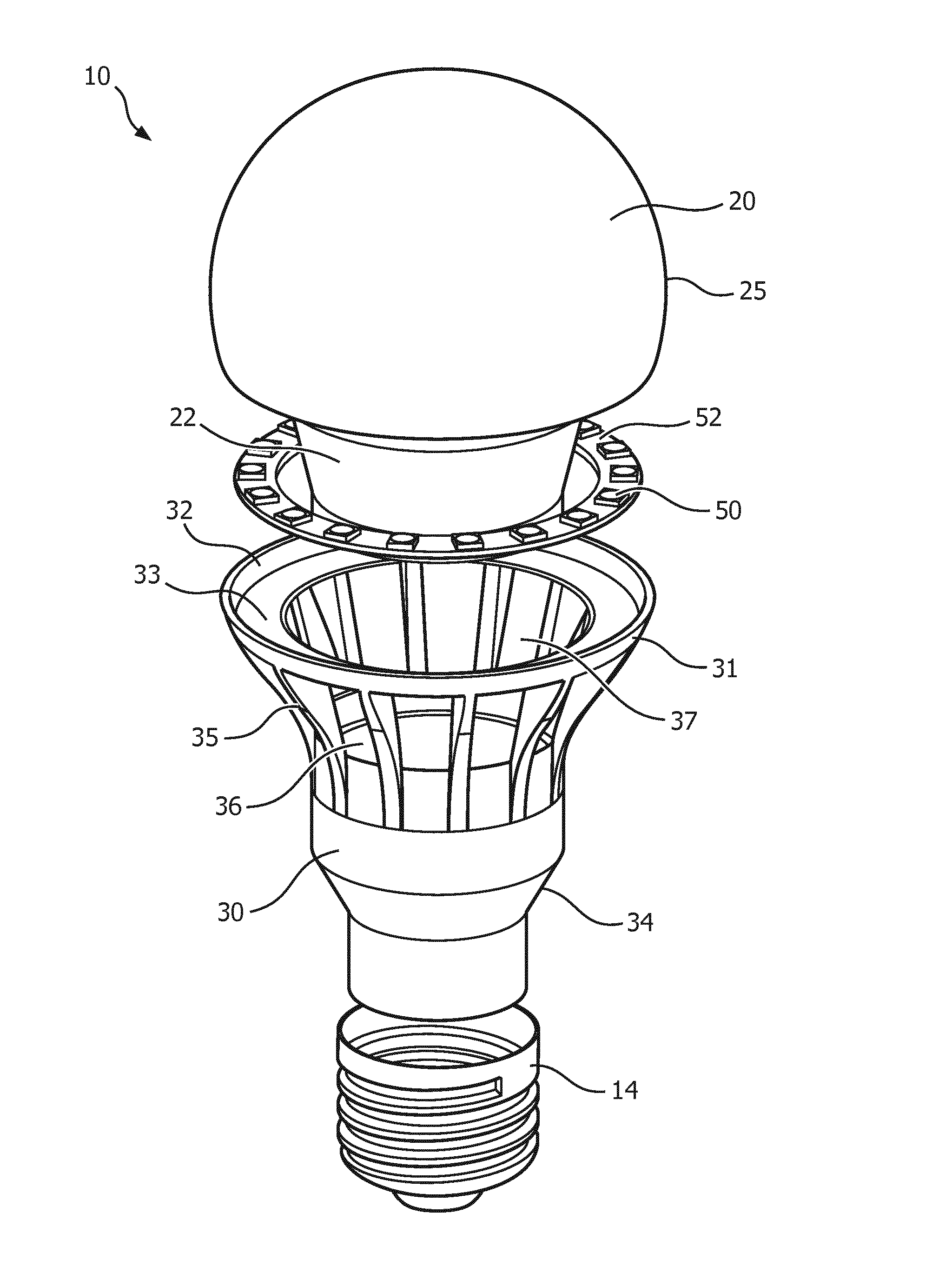
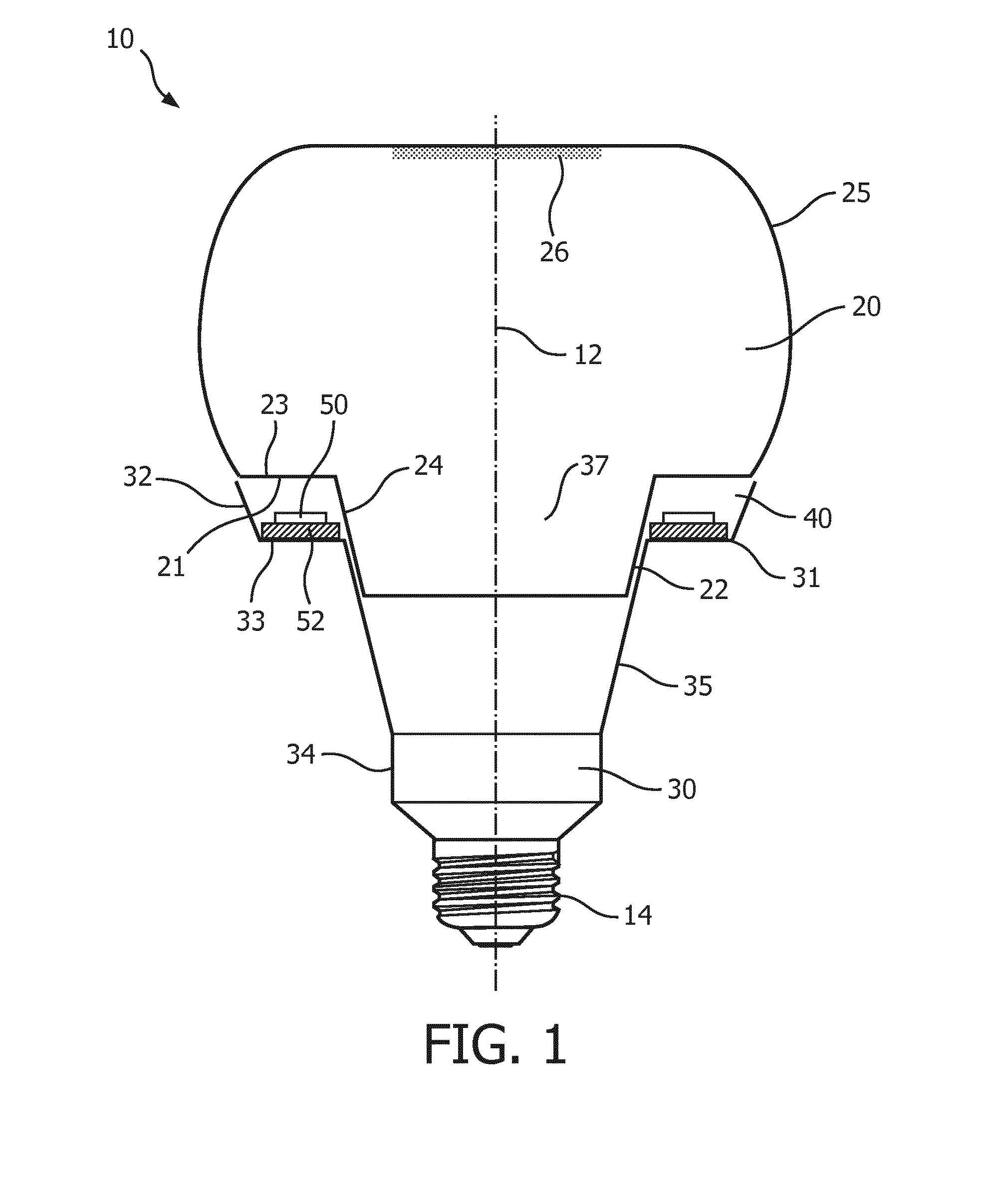
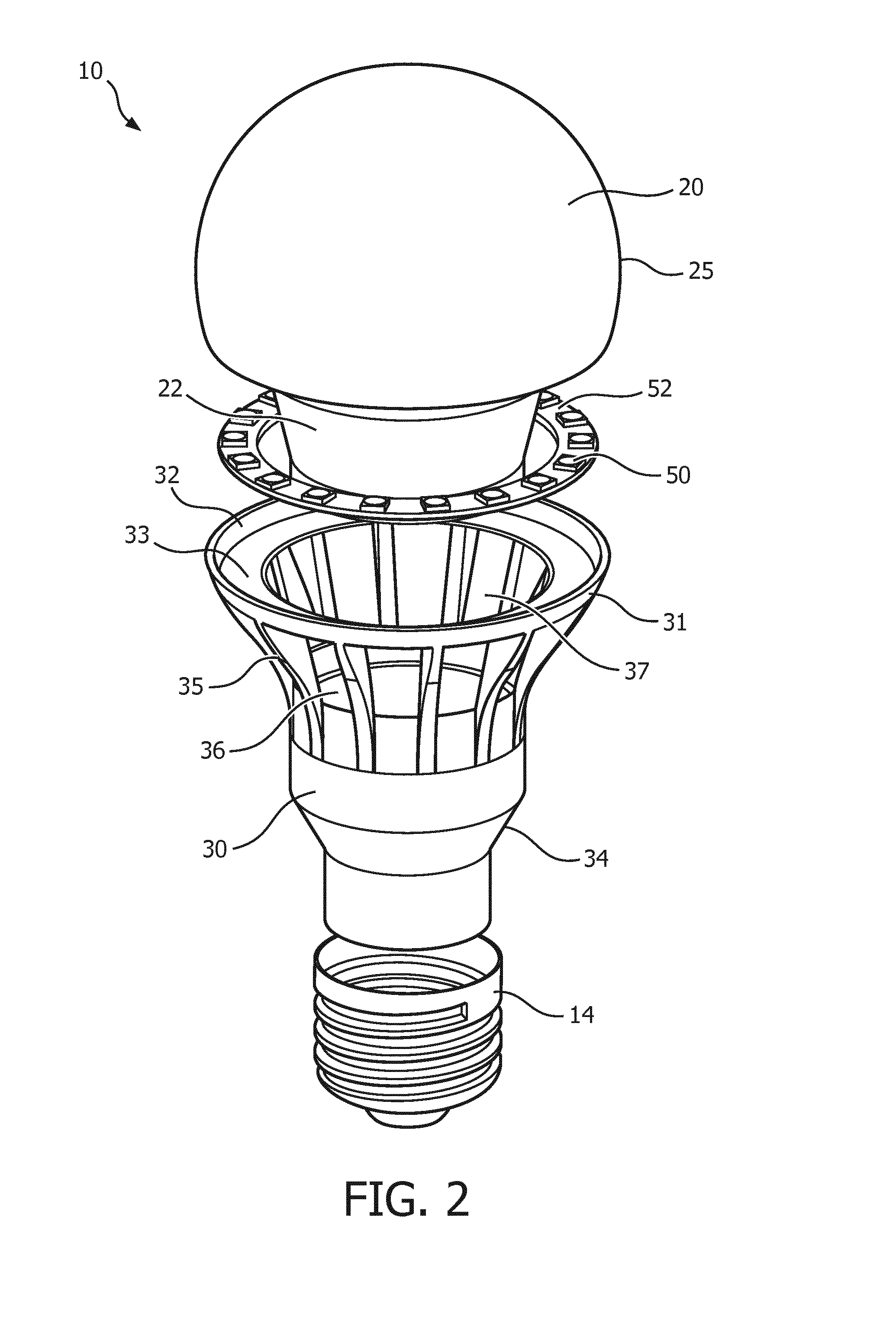
[0035]It should be understood that the Figures are merely schematic and are not drawn to scale. It should also be understood that the same reference numerals are used throughout the Figures to indicate the same or similar parts.

[0036]A cross-section of an embodiment of a lighting device 10 according to the present invention is schematically depicted in FIG. 1. FIG. 2 schematically depicts the lighting device of FIG. 1 in an exploded view and FIG. 3 schematically depicts the lighting device of FIG. 1 in a perspective view. The same reference numerals in these figures are depicting the same elements unless explicitly stated otherwise.

[0037]The lighting device 10 comprises a bulbous member 20 engaging with a heat sink 30 to form the overall shape of the lighting device 10. The bulbous member 20 is typically made of a material through which light can travel, such as glass or an optical grade polymer, for example polycarbonate, PMMA, PET or the like. The material may be transparent or tr...


PUM

PropertyMeasurementUnit
Fractionaaaaaaaaaa
Thicknessaaaaaaaaaa
Diameteraaaaaaaaaa

Abstract

Disclosed is a lighting device (10) comprising a heat sink (30) having an annular portion (31) including an annular surface portion (33) delimiting a central aperture (37), said annular surface portion (33) carrying a plurality of SSL elements (50); and a bulbous member (20) cooperating with the heat sink (30), said bulbous member (20) having a first surface portion (21) opposite said SSL elements (50) and a second surface portion (22) extending from said first surface portion (21) through said central aperture (37); wherein the bulbous member (20) is used as a light guide member for light emitted by the plurality of SSL elements (50). A luminaire including such a lighting device (10) is also disclosed.

Description

FIELD OF THE INVENTION[0001]The present invention relates to a lighting device comprising a heat sink having an annular surface portion delimiting a central aperture, said annular surface portion carrying a plurality of SSL elements; and a bulbous member cooperating with the heat sink.[0002]The present invention further relates to a luminaire comprising such a lighting device.BACKGROUND OF THE INVENTION[0003]With a continuously growing population, it is becoming increasingly difficult to meet the world's energy needs and, simultaneously, to control carbon emissions to kerb greenhouse gas emissions which are considered responsible for global warming phenomena. These concerns have triggered a drive towards a more efficient use of electricity in an attempt to reduce energy consumption.[0004]One such area of concern is lighting applications, either in domestic or commercial settings. There is a clear trend towards the replacement of traditional, relatively energy-inefficient, light bulb...

Claims


Application Information

Patent Timeline
IPC IPC(8): F21K9/61F21V3/04F21V29/77F21K9/232F21V3/02
CPCF21K9/61F21K9/232F21V3/02F21Y2113/13F21V3/0445F21Y2115/10F21V29/773F21V7/22F21V29/70F21V3/061F21V3/0615F21V3/062F21V3/0625F21V7/24F21V7/28F21Y2103/33F21K99/00
Inventor LI, HONGXIAXIONG, YANHE, YEMEILIN, SHI DONGJIANG, QINGQINGSHI, HAOYANG
Owner SIGNIFY HOLDING B V
Why Eureka
Eureka Blog
Learn More