Wavelength conversion device

a conversion device and wavelength technology, applied in the direction of projectors, instruments, mirrors, etc., can solve the problems of poor stability of metal reflective layers, significant increase in cost, and reduced film reliability, so as to improve the total output brightness, simple process, and low cost

Active Publication Date: 2017-02-16
DELTA ELECTRONICS INC
View PDF6 Cites 5 Cited by
  • Summary
  • Abstract
  • Description
  • Claims
  • Application Information

AI Technical Summary

Benefits of technology

[0027]Accordingly, in the reflective member of the wavelength conversion device of the present disclosure, the nano particles are dispersively distributed in the continuous-phase material, and light can be reflected at the interface between the continuous-phase material and any nano particle because the refractive index difference between the continuous-phase material and the nano particles. By adjusting the particle diameter and the concentration of the nano particles, a reflection mechanism similar to the conventional dielectric multi-layer reflective film can be achieved, so that the reflective requirements of full incident angles and full wavelength spectrums can be met. Furthermore, the wavelength conversion device of the present disclosure can effectively enhance the total output brightness by preparing the reflective member with an appropriate recipe on the substrate, so that the wavelength conversion device further has advantages of simple processes and low cost.

Problems solved by technology

When the film-coating process is complicated, reliability of the films is decreased and the cost is significantly increased.
Although the metal reflective layer may not need to consider the incident angle, yet the metal reflective layer is easily oxidized and corroded, and thus the stability of the metal reflective layer is poor.
Owing to the Brewster Angle Effect, a portion of the incident light with a large incident angle may be polarized and penetrate the highly reflective layer and be absorbed by the substrate, thus decreasing the light output of the phosphor powder color wheel.

Method used


Image

  • Wavelength conversion device
  • Wavelength conversion device
  • Wavelength conversion device

Examples


Embodiment Construction

[0034]Reference will now be made in detail to the present embodiments of the present disclosure, examples of which are illustrated in the accompanying drawings. Wherever possible, the same reference numbers are used in the drawings and the description to refer to the same or like parts.

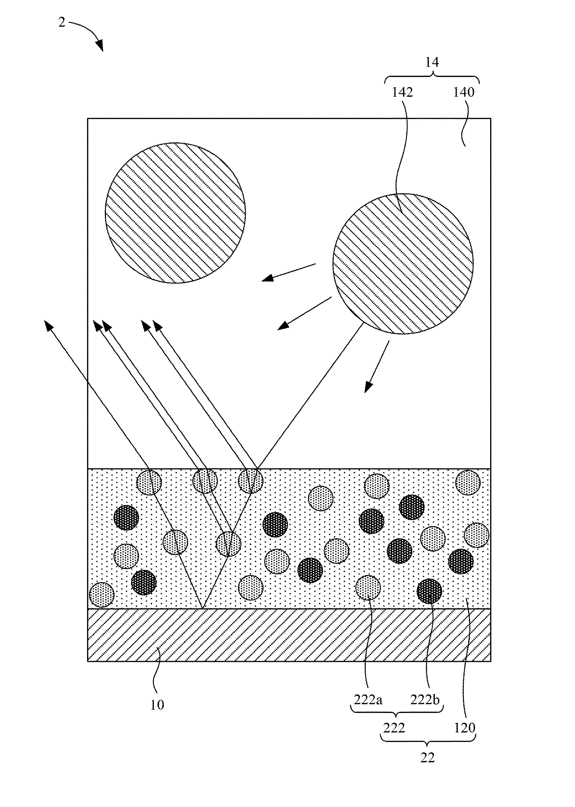
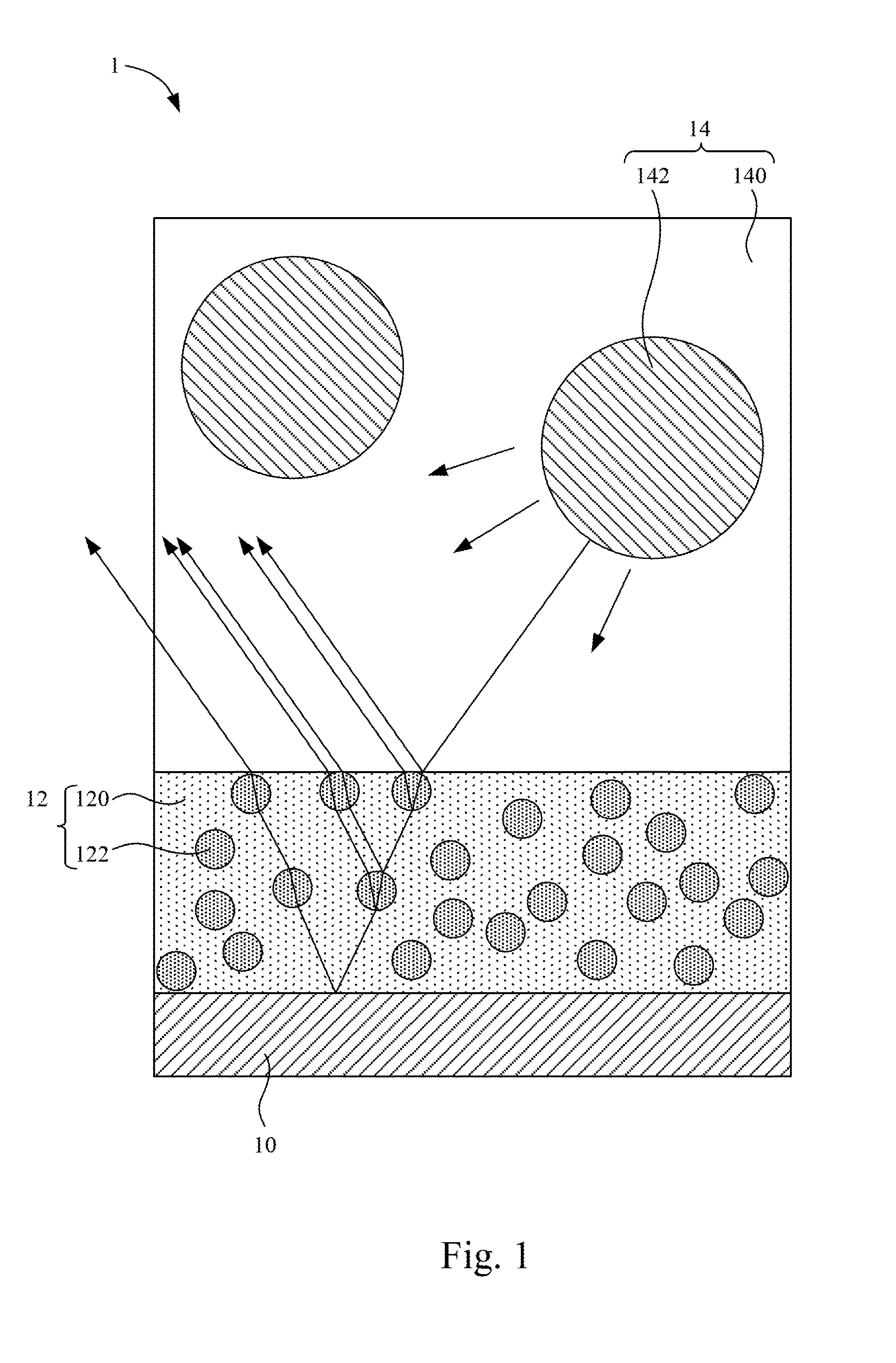
[0035]Reference is made to FIG. 1. FIG. 1 is a schematic diagram of a wavelength conversion device 1 according to an embodiment of the present disclosure.

[0036]As shown in FIG. 1, in the embodiment, the wavelength conversion device 1 includes a substrate 10, a reflective member 12, and a wavelength conversion member 14. The reflective member 12 is disposed on the substrate 10. The reflective member 12 includes a continuous-phase material 120 and nano particles 122. The nano particles 122 are dispersively distributed in the continuous-phase material 120. A refractive index of the continuous-phase material 120 is different from a refractive index of the nano particles 122. The wavelength conversion memb...


PUM


Abstract

A wavelength conversion device includes a substrate, a reflective member, and a wavelength conversion member. The reflective member is disposed on the substrate and includes a continuous-phase material and nano particles. The nano particles are distributed in the continuous-phase material. A refractive index of the continuous-phase material is different from a refractive index of the nano particles. The wavelength conversion member is disposed on the reflective member. The reflective member is configured to reflect the light converted from the wavelength conversion member to output.

Description

RELATED APPLICATIONS[0001]This application claims priority to U.S. Provisional Application Ser. No. 62 / 203,401, filed Aug. 11, 2015 and Taiwan Application Serial Number 105100468, filed Jan. 8, 2016, which are herein incorporated by reference.BACKGROUND[0002]Technical Field[0003]The present disclosure relates to a wavelength conversion device, and more particularly, to a color wheel device.[0004]Description of Related Art[0005]A conventional color wheel with reflective phosphor powder includes a substrate coated with a highly reflective layer, and phosphor powder is coated on the highly reflective layer. The highly reflective layer is configured to forwardly reflect the light generated by exciting the phosphor powder with laser. In general, a metal reflective layer, a dielectric multi-layer reflective film, or a metal / dielectric multi-layer reflective film can be used as the highly reflective layer.[0006]However, the performance of the color wheel with reflective phosphor powder is ...

Claims


Application Information

Patent Timeline
Patent Type & Authority Applications(United States)
IPC IPC(8): G02B26/00G02B5/22G02B5/08
CPCG02B26/008G02B5/08G02B5/226G02B5/223G02B5/22G02B5/0242G02B5/0284G02B5/0294G03B21/204G02B5/26
Inventor CHANG, KEH-SUCHOU, YEN-ICHEN, CHILU, CHUN-HSIEN
Owner DELTA ELECTRONICS INC
Why Eureka
Try Eureka