Transmission device, reception device, transmission method, and reception method

a technology of transmission device and reception device, which is applied in the direction of data switching network, digital transmission, transportation and packaging, etc., can solve the problem of not being able to simply determine, and achieve the effect of suppressing the increase in the load of network resources and improving security

Inactive Publication Date: 2017-02-16
PANASONIC INTELLECTUAL PROPERTY MANAGEMENT CO LTD
View PDF2 Cites 8 Cited by
  • Summary
  • Abstract
  • Description
  • Claims
  • Application Information

AI Technical Summary

Benefits of technology

[0008]According to the present invention, security can be improve...

Problems solved by technology

Therefore, in a reception node, it is not possible to simply determine ...

Method used


Image

  • Transmission device, reception device, transmission method, and reception method
  • Transmission device, reception device, transmission method, and reception method
  • Transmission device, reception device, transmission method, and reception method

Examples


Embodiment Construction

[0052]Prior to the description of the exemplary embodiment of the present invention, problems of a conventional device will be briefly described. When a MAC is generated each time when the ordinary message is generated / transmitted, the load of the node becomes large and the power consumption also increases. Further, because the number of messages increases, a bus occupation rate also increases.

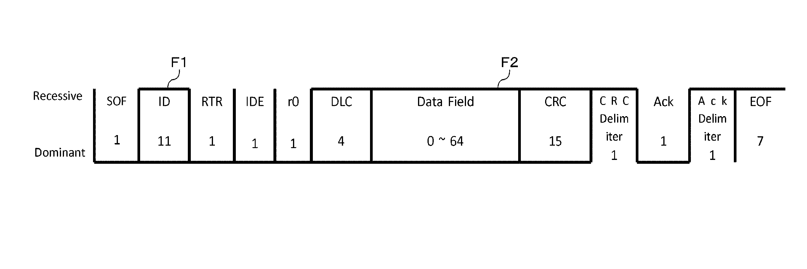
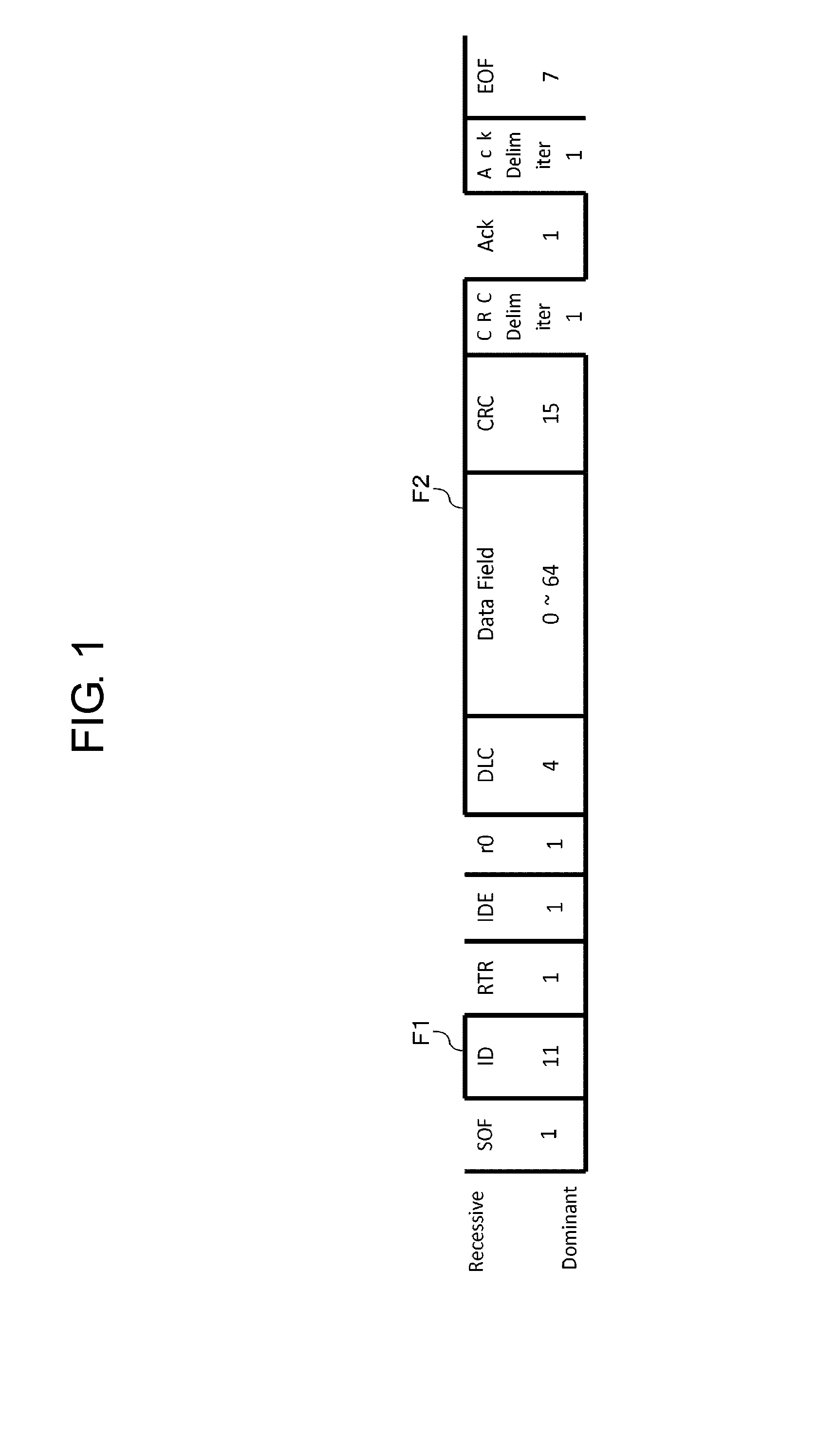
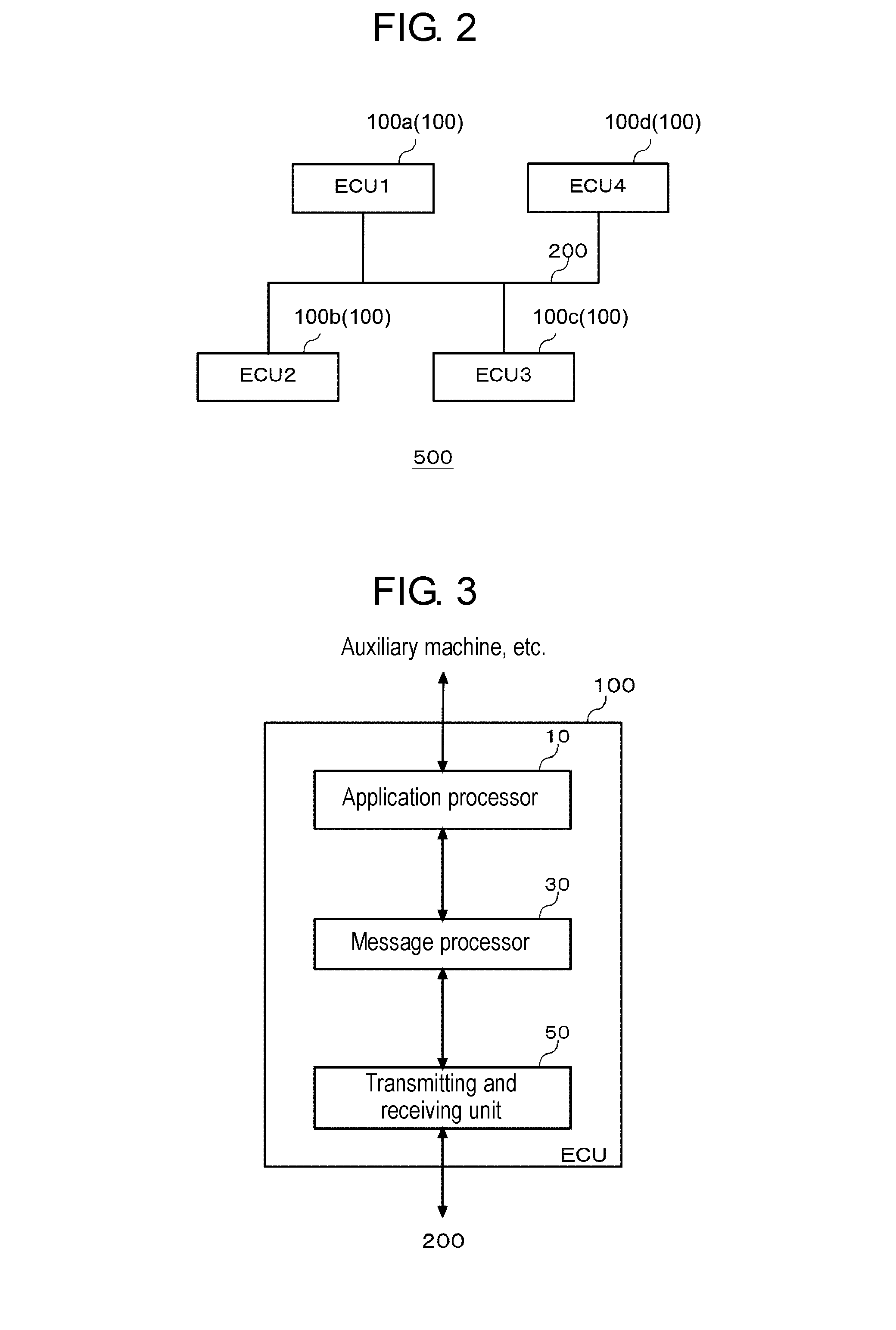
[0053]Hereinafter, a transmission device and a reception device according to an exemplary embodiment of the present invention will be described. The exemplary embodiment of the present invention relates to an in-vehicle network in which a plurality of ECUs (Electronic Control Units) mounted in a vehicle are connected as nodes, and a message containing a message identifier (ID), data, and the MAC is broadcast. Hereinafter, the exemplary embodiment of the present invention will be described by exemplifying a CAN system as such a network. As described above, the CAN employs a bus type network, an...


PUM


Abstract

A transmission device has a first generator, a second generator, and a transmitter. The first generator generates data to be broadcast-transmitted. The second generator generates a message authentication code for at least the data generated in the first generator. The transmitter broadcast-transmits the data generated in the first generator, and the message authentication code generated in the second generator. The second generator omits generating message authentication codes for one or some of a plurality of pieces of data generated in the first generator.

Description

TECHNICAL FIELD[0001]The present invention relates to a transmission device and a reception device in a communication system which are connected by a bus, a transmission method, and a reception method.BACKGROUND ART[0002]As an in-vehicle network, a CAN (Controller Area Network) is popular. The CAN is a serial communication protocol employing a bus type network. Messages from each node connected to the bus are broadcast to all nodes connected to the bus. The messages do not include identification information of a transmission source node and a destination node. Therefore, in a reception node, it is not possible to simply determine whether a received message is a message from a correct communication partner.[0003]In order to ensure integrity of a message and to prevent a replay attack from an unauthorized device connected to the CAN, a method using a message authentication code (MAC) is proposed. For example, there is proposed a method for generating the MAC for an ordinary message, a...

Claims


Application Information

Patent Timeline
IPC IPC(8): H04L29/06H04L12/40B60R16/023
CPCH04L63/0876H04L2012/40215H04L12/40B60R16/023H04L9/3242H04L2012/40273H04L63/123H04L9/32H04L12/28
Inventor TANABE, MASATOANZAI, JUNKITAMURA, YOSHIHIKO
Owner PANASONIC INTELLECTUAL PROPERTY MANAGEMENT CO LTD
Why Eureka
Try Eureka