Eureka AIR delivers breakthrough ideas for toughest innovation challenges, trusted by R&D personnel around the world.

Steering system

Active Publication Date: 2017-02-23
JTEKT CORP
View PDF2 Cites 7 Cited by
  • Summary
  • Abstract
  • Description
  • Claims
  • Application Information

AI Technical Summary

Benefits of technology

The invention is a steering system that aims to prevent damage to a rack bush which is located close to a guide member. The technical effect of this invention is to prolong the life of the steering system and to maintain its performance.

Problems solved by technology

In the rack shaft, particularly, backlash is likely to occur at a portion pressed by the guide member such as the rack guide.
If a long term load or a sudden large load is applied to the rack bush disposed close to the guide member, distortion or abrasion may occur, which causes deterioration of the rack bush.

Method used


Image

  • Steering system
  • Steering system
  • Steering system

Examples


Embodiment Construction

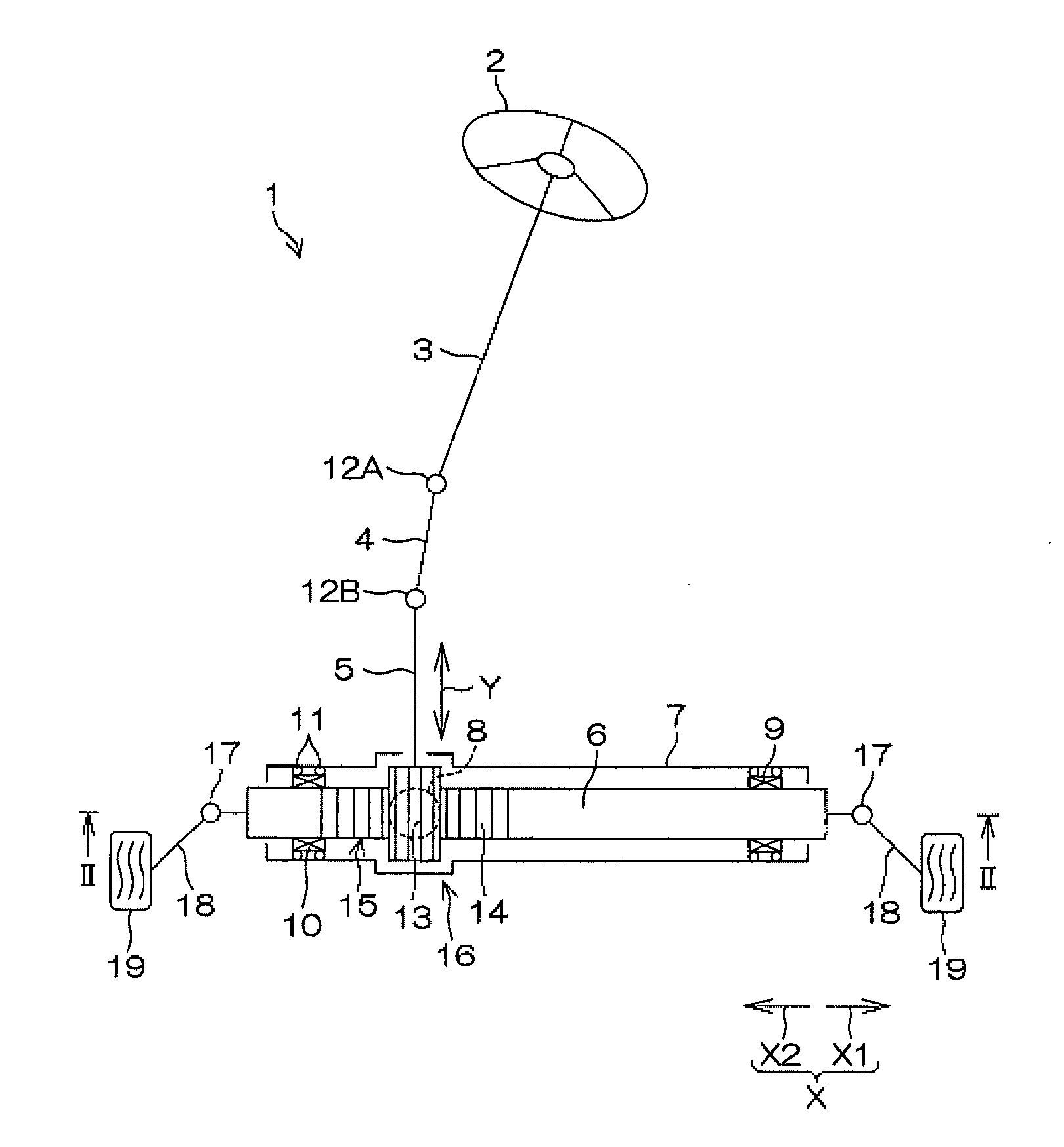
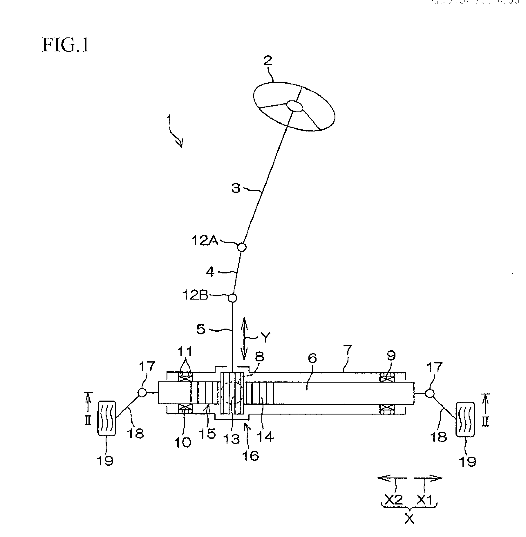
[0019]Hereinafter, an embodiment of the invention will be described with reference to the accompanying drawings. FIG. 1 is a schematic front view of a steering system 1 according to an embodiment of the invention. Referring to FIG. 1, a steering system 1 mainly includes a steering member 2, a steering shaft 3, an intermediate shaft 4, a pinion shaft 5, a rack shaft 6, a housing 7, a guide mechanism 8, a first rack bush 9, a second rack bush 10, and an elastic member 11. In FIG. 1, the guide mechanism 8 is disposed farther away from the viewer than the rack shaft 6, and is shown by a dashed line.

[0020]As the steering member 2, for example, a steering wheel can be used. One end of the steering shaft 3 is coupled to the steering member 2. The other end of the steering shaft 3 is coupled to one end of the intermediate shaft 4 via a universal joint 12A. The other end of the intermediate shaft 4 is coupled to one end of the pinion shaft 5 via a universal joint 12B. A plurality of pinion t...


PUM


Abstract

In a steering system, a guide member faces the rack shaft on the opposite side of the rack shaft from the pinion shaft, and an opposed member faces the guide member at a first distance. The rack shaft is supported by the first rack bush so as to be slidable in the axial direction. The rack shaft is supported so as to be slidable in the axial direction X at a position closer to the guide member than the first rack bush is by the second rack bush disposed away from the inner surface. An elastic member that can be elastically deformed is disposed between the inner surface and the second rack bush. The second rack bush has an opposed portion disposed on the opposite side of the rack shaft from the pinion shaft and facing the inner surface at a second distance that is larger than the first distance.

Description

INCORPORATION BY REFERENCE[0001]The disclosure of Japanese Patent Application No. 2015-163914 filed on Aug. 21, 2015 including the specification, drawings and abstract is incorporated herein by reference in its entirety.BACKGROUND OF THE INVENTION[0002]1. Field of the Invention[0003]The invention relates to a steering system.[0004]2. Description of Related Art[0005]A rack that meshes with a pinion of a pinion shaft is formed on a rack shaft of a rack and pinion steering system described in Japanese Patent Application Publication No. 2012-188005 (JP 2012-188005 A). The pinion shaft is supported by a gear housing. The rack shaft is inserted into a through hole that runs through the gear housing. Both ends of the rack shaft are coupled to wheels through a ball joint, etc. The pinion and the rack convert the rotational motion of a steering wheel into an axial motion of the rack shaft. The rack shaft is pressed against the pinion shaft by a rack guide from the back of the rack shaft, or ...

Claims


Application Information

Patent Timeline
IPC IPC(8): B62D3/12F16H55/28
CPCB62D3/126F16H2055/281F16H55/28B62D3/12B62D3/123F16H55/283
Inventor KAWAKUBO, AKITAKE
Owner JTEKT CORP
Why Eureka
Eureka Blog
Learn More