Composite polarizing plate and liquid crystal display using the same

a technology of liquid crystal display and polarizing plate, which is applied in the direction of polarizing elements, instruments, optics, etc., can solve the problems of difficult retardation, poor adhesive properties, and inability to obtain desired adhesive force in some cases, so as to suppress the increase the resin pressure, and suppress the effect of deterioration and decomposition of polypropylene resin

Inactive Publication Date: 2009-03-12
SUMITOMO CHEM CO LTD
View PDF6 Cites 17 Cited by
  • Summary
  • Abstract
  • Description
  • Claims
  • Application Information

AI Technical Summary

Benefits of technology

[0051]A polypropylene resin is formed into a film by an method to obtain a raw film. This raw film is transparent and substantially has no in-plane retardation. For example, a raw film of a polypropylene resin substantially having no in-plane retardation can be obtained by an extrusion molding method using a molten resin, a solvent casting method of forming a film by pouring a resin dissolved in an organic solvent to a flat plate and removing the solvent, and the like.
[0052]A method for producing a raw film by extrusion molding will be described in detail. A polypropylene resin is melted and kneaded by rotation of a screw in an extruder and extruded in a sheet-like shape from a T die. The temperature of the extruded molten-state sheet is about 180 to 300° C. If the temperature of the molten-state sheet is under 180° C., the spreadability is not sufficient and the thickness of the film to be obtained becomes uneven and thus the film may possibly be uneven in retardation. In addition, if the temperature exceeds 300° C., the resin tends to be deteriorated or decomposed to generate foams in the sheet or include carbides in some cases.
[0053]The extruder may be a uniaxial extruder or a biaxial extruder. For example, in the case of a uniaxial extruder, usable are screws with a ratio L / D of length L and diameter D in a range of around 24 to 36, a compression ratio (former / latter) of space volume of a screw groove in a resin supply part and space volume of a screw groove in a resin measurement part in a range of around 1.5 to 4 and of types such as a full flight type, a barrier type and also a Madoc type having kneading part. In terms of suppression of deterioration and decomposition of polypropylene resin and evenness of melting and kneading, it is preferable to use screws of a barrier type having L / D in a range of 28 to 36 and a compression ratio of 2.5 to 3.5, Further, to suppress deterioration and decomposition of the polypropylene resin as much as possible, it is preferable to keep the inside of the extruder in nitrogen atmosphere or vacuum. Furthermore, to remove a volatile gas generated by deterioration or decomposition of the polypropylene resin, it is also preferable to provide an orifice of 1 mmφ or more and 5 mmφ or less at the tip end of the extruder to increase the resin pressure at the tip end part of the extruder. To increase the resin pressure to the orifice at the tip end part of the extruder means to increase the back pressure at the tip end and accordingly the stability of extrusion can be improved. The diameter of the orifice to be employed may be preferably 2 mmφ or more and 4 mmφ or less.
[0054]The T die used for extrusion is preferably a die which is free from slight steps or scratches on the flow channel surface of the resin and whose lip part is plated or coated with a material having a small friction coefficient with the melted polypropylene resin and further has a sharp edge-like shape polished to be 0.3 mmφ or less. Examples of materials with a small friction coefficient include tungsten carbide and fluoro specialized plating. Use of such a T die suppresses occurrence of eye discharges and at the same time suppresses die line formation, so that a resin film excellent in appearance uniformity can be obtained. This T die is preferable to have a manifold with a coat hunger shape and satisfy the following condition (1) or (2) and more preferable to satisfy the following condition (3) or (4):
[0055]By using such a T die satisfying such conditions alligns the flow of molten-state polypropylene resin in order in the inside of the T die and also makes it possible to carry out extrusion with suppressed thickness unevenness even in the lip part and accordingly, a raw film excellent in the thickness precision and even retardation can be obtained.
[0056]In terms of suppression of the extrusion alteration of the polypropylene resins it is preferable to attach a gear pump between the extruder and the T die through an adaptor interposed therebetween. Further, to remove foreign matter contained in the polypropylene resin, it is also preferable to attach a leaf disk filter.

Problems solved by technology

Here, in the case where a birefringence film is used as a protection layer of a polarizing plate, the photoelasticity and the oriented birefringence are said to have substantially no correlation; however when materials with low photoelastic coefficient are selected to suppress blanking, it becomes difficult to exhibit retardation at the time of stretching in many materials and only a thick film is used to exhibit desired retardation value.
On the other hand, if materials with low moisture permeability are selected to suppress change in demension of a polarizing plate due to moisture absorption and desorption, the adhesive property is often worse and desired adhesive force cannot be obtained in some cases.

Method used


Image

  • Composite polarizing plate and liquid crystal display using the same
  • Composite polarizing plate and liquid crystal display using the same
  • Composite polarizing plate and liquid crystal display using the same

Examples


example 1

(a) Preparation of Adhesive

[0102]A water-based adhesive of the following composition was prepared. This was used as a water-based epoxy adhesive. Polyvinyl alcohol resin 3 parts

(“KL-318” made available by Kuraray Co., Ltd.)

Water-soluble polyamide epoxy resin 1.5 parts

(“Sumirez Resin 650” made available by Sumitomo Chemtex Co., Ltd., aqueous solution of 30% solid matter concentration) Water 100 parts

[0103]Further, another water-based adhesive of the following composition was prepared. This was used as a urethane type adhesive.

Polyester type ionomer urethane resin 30 parts

(“Hydran AP-20” made available by DIC Corporation, aqueous solution of 30% solid matter concentration)

Isocyanate type crosslinking agent 7.5 parts

(“Hydran Assister C-1” made available by DIC Corporation) Water 5 parts

[0104]Further, “Aron Alpha”, a cyanoacrylate type instant adhesive commercialized by Konishi Co., Ltd. was used as another adhesive.

[0105]Furthermore, as another adhesive, a solvent-free type epoxy ultra...

example 2

[0109]After a film was produced by melting and extruding the crystalline polypropylene type resin of the propylene / ethylene random copolymer same as that used in Example 1, the film was stretched by successive biaxial stretching in order to vertical stretching and transverse stretching to obtain a retardation with a thickness of 21 μm and Ro=60 nm and Rth=115 nm. A polarizer comprising a protection layer of a triacetyl cellulose film stuck to one face of a polyvinyl alcohol / iodine type polarizer was prepared and the retardation film obtained in the above-mentioned manner was stuck to the polarizer face by the water-based epoxy adhesive described in Example 1 to obtain a composite polarizing plate. The thickness of the composite polarizing plate was 122 μm and was thus made thinner than that of a polarizer obtained by sticking a protection layer of a 80 μm-thick triacetyl cellulose film to both face of the polarizer. If a 40 μm-thick triacetyl cellulose film was used, the thickness o...

example 3

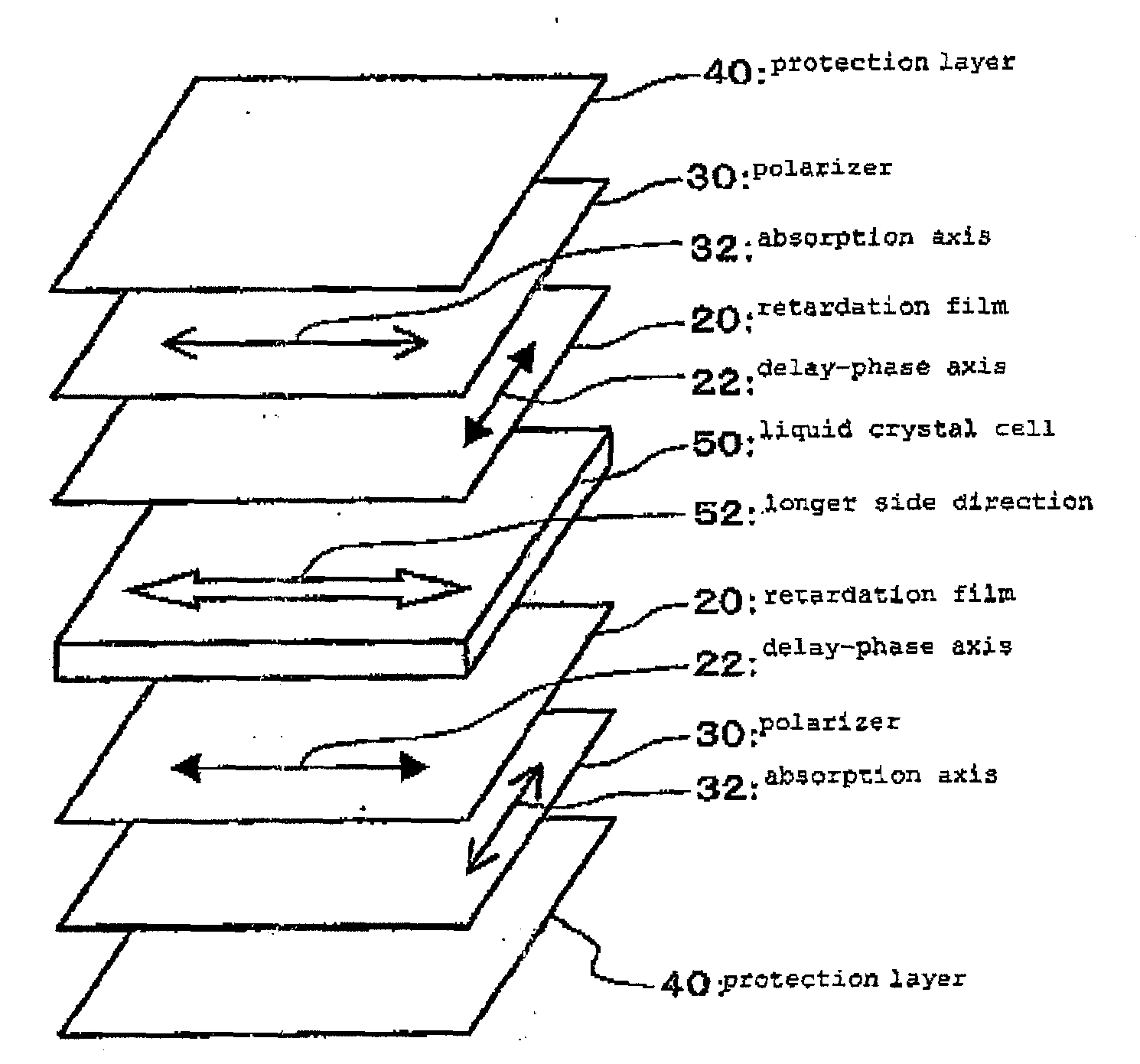
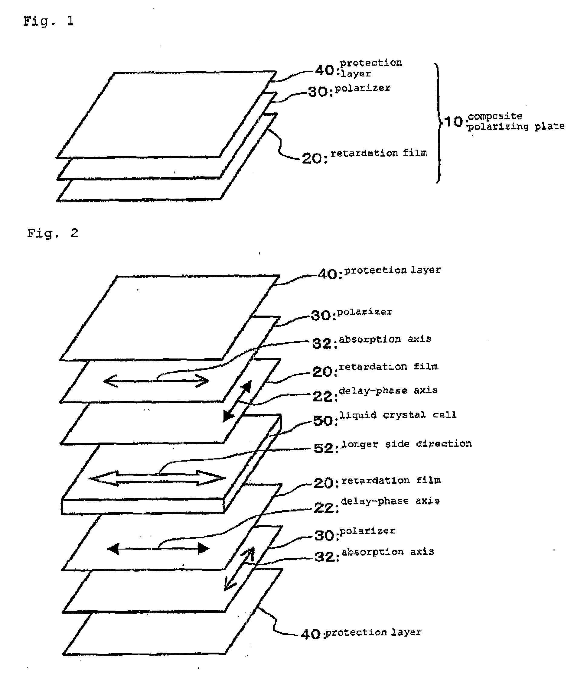
[0110]After a film was produced from the same propylene / ethylene random copolymer as that used in Example 1, successive biaxial stretching was carried out to obtain a biaxial retardation film. This retardation film has R0=55 nm and Rth=115 nm. Corona discharge treatment was carried out for the surface of this retardation film. The corona discharge treated-face of the retardation film was stuck to one face of a polyvinyl alcohol / iodine type polarizer and a triacetyl cellulose film treated by saponification was stuck to the other face of the polarizer using the water-based epoxy adhesive shown in Example 1 and thereafter, drying at 80° C. for 5 minutes was carried out and curing at 40° C. for about 60 hours was carried out to obtain a composite polarizing plate. At that time, the absorption axis of the polarizer and the delay-phase axis of the retardation film were arranged to be rectangular each other.

[0111]Next, “BRAVIA 32”, a liquid crystal television, manufactured by Sony was disa...


PUM

PropertyMeasurementUnit
thicknessaaaaaaaaaa
thicknessaaaaaaaaaa
thicknessaaaaaaaaaa

Abstract

Disclosed is a composite polarizing plate wherein a transparent protection layer (40) is formed on one side of a polarizer (30) which is composed of a polyvinyl alcohol resin and a retardation film (20) composed of a polypropylene resin is bonded to the other side of the polarizer (30), which is opposite to the side on which the transparent protection layer (40) is formed. The retardation film (20) composed of a polypropylene resin may be made of a homopolymer of propylene, or alternatively made of a copolymer with another monomer which mainly consists of propylene. A liquid crystal display is obtained by arranging this composite polarizing plate on at least one side of a liquid crystal cell (50).

Description

TECHNICAL FIELD[0001]The present invention relates to a composite polarizing plate and a liquid crystal display using the same. More particularly, the present invention relates to a composite polarizing plate useful for providing a liquid crystal display excellent in a field angle property and a liquid crystal display using the same.BACKGROUND ART[0002]In recent years, lightweight and thin flat liquid crystal displays being low-consumption of electric power and operable at low voltage have rapidly become popular as display devices for information such as mobile phones, portable information terminals, monitors for computers, televisions, or the like. Along with developments of liquid crystal techniques, liquid crystal displays of various modes have been proposed and problems of liquid crystal displays such as response speed, contrast, and a narrow field angle have been resolved. However, it has been still pointed out that a field angle as compared with that of cathode ray tubes (CRT)...

Claims


Application Information

Patent Timeline
Patent Type & Authority Applications(United States)
IPC IPC(8): G02F1/1335G02B1/08
CPCG02B5/305G02B5/3083G02F2201/54G02F1/133528G02F1/13363G02B27/281G02B5/30G02F1/1335
Inventor KUNAI, YUICHIROMATSUOKA, YOSHIKIKUROIWA, HIDEONAGASHIMA, TOHRUINOKUCHI, YUUHEI
Owner SUMITOMO CHEM CO LTD
Why Eureka
Try Eureka