
Time-of-Flight Recognition System for a Bathroom Fixture

a recognition system and bathroom technology, applied in the direction of process and machine control, using reradiation, instruments, etc., can solve the problems of missing users, affecting the detection accuracy of users, so as to improve detection accuracy and reduce system noise.

Inactive Publication Date: 2017-02-23
ZURN INDS
View PDF4 Cites 21 Cited by
  • Summary
  • Abstract
  • Description
  • Claims
  • Application Information

AI Technical Summary

Benefits of technology

The patent describes a method for detecting photons using a time-of-flight sensor. The method involves setting a detection zone based on the distance of the photons from the sensor. The detected photons are clustered around a specific wavelength, which helps improve detection accuracy. The method also includes optical filtering to determine if the detected photons are correlated or uncorrelated, which helps to avoid false positive detection of objects. Additionally, an ambient light sensor is used to detect and account for ambient light conditions, which reduces system noise. The technical effects of this patent are improved detection accuracy and reduced system noise.

Problems solved by technology

Typical infrared sensors suffer from at least three primary drawbacks.
For example, a typical infrared sensor used in a sink installation may detect a dirty sink surface as a false positive resulting in undesirable functionality.
This line-of-sight detection zone can lead to missed users and false detections.
The infrared sensor will react differently to varying colors and textures leading to inconsistent or undesirable operation.
Finally, ambient light can heavily affect the performance of typical infrared sensors.
This leads to increased installation costs and installer dependence, leading to inconsistency of operation.

Method used


Image

  • Time-of-Flight Recognition System for a Bathroom Fixture
  • Time-of-Flight Recognition System for a Bathroom Fixture
  • Time-of-Flight Recognition System for a Bathroom Fixture

Examples


Embodiment Construction

[0033]Before the present invention is described in further detail, it is to be understood that the invention is not limited to the particular aspects described. It is also to be understood that the terminology used herein is for the purpose of describing particular aspects only, and is not intended to be limiting. The scope of the present invention will be limited only by the claims. As used herein, the singular forms “a”, “an”, and “the” include plural aspects unless the context clearly dictates otherwise.

[0034]It should be apparent to those skilled in the art that many additional modifications beside those already described are possible without departing from the inventive concepts. In interpreting this disclosure, all terms should be interpreted in the broadest possible manner consistent with the context. Variations of the term “comprising”, “including”, or “having” should be interpreted as referring to elements, components, or steps in a non-exclusive manner, so the referenced e...


PUM


Abstract

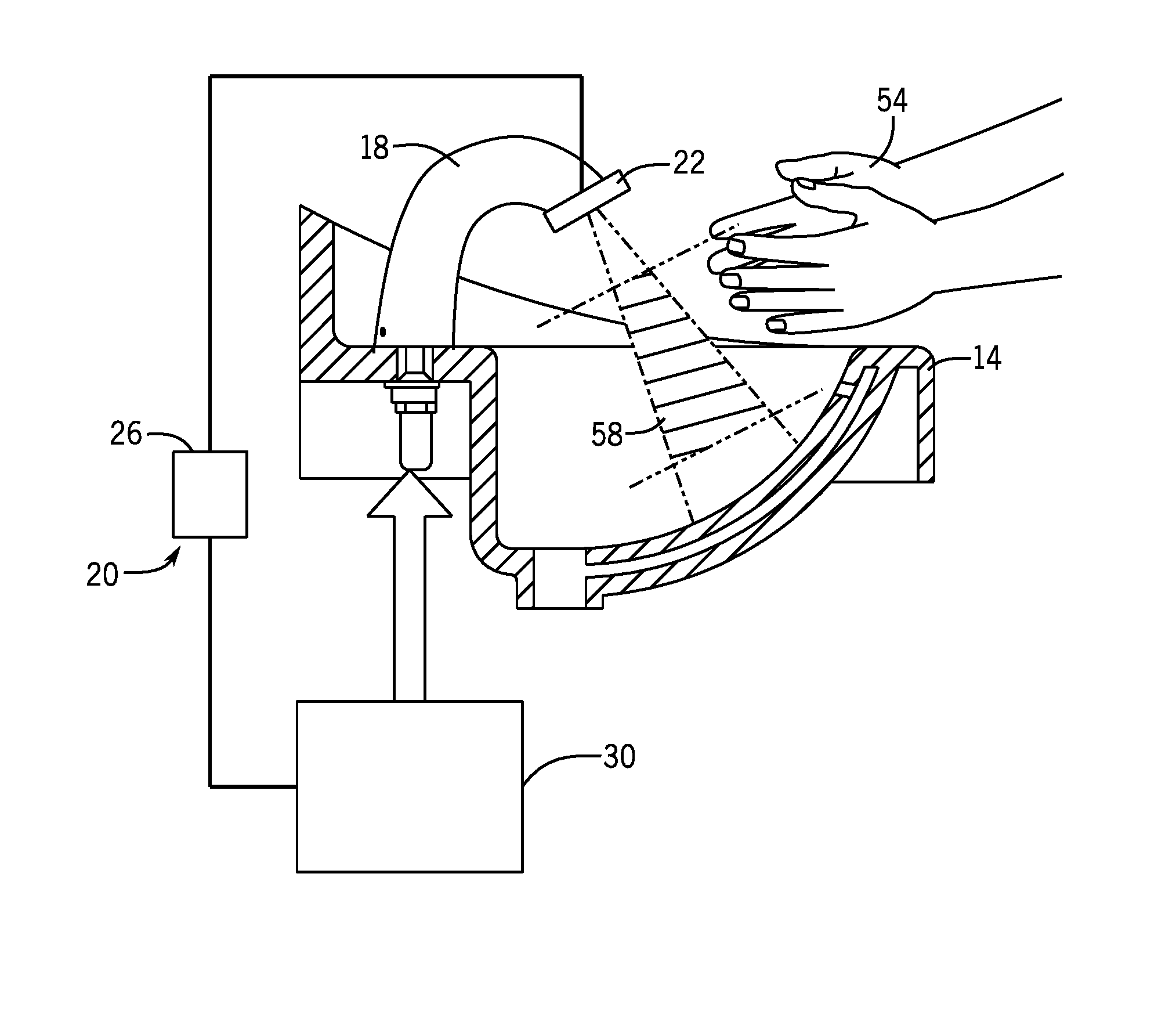
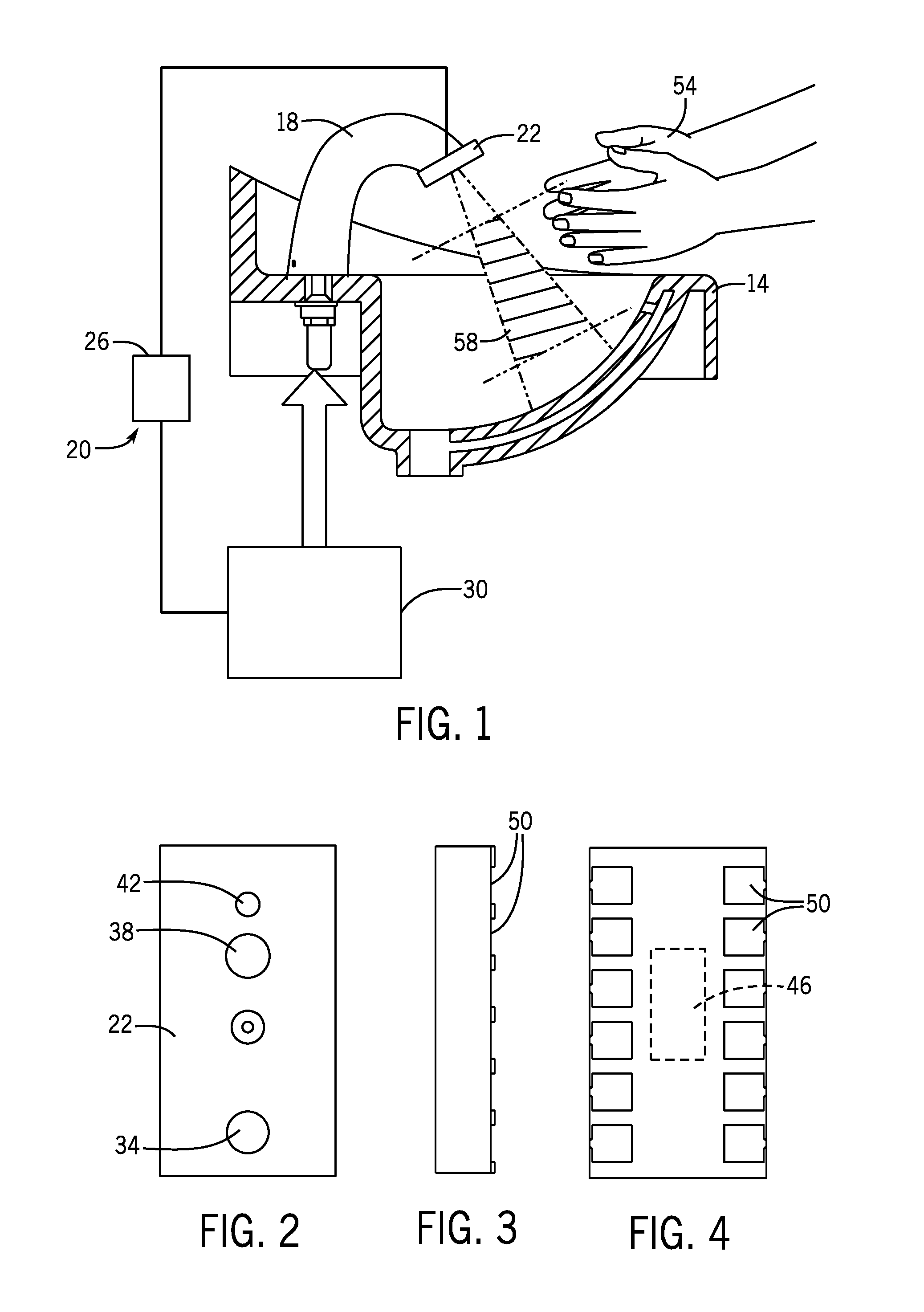
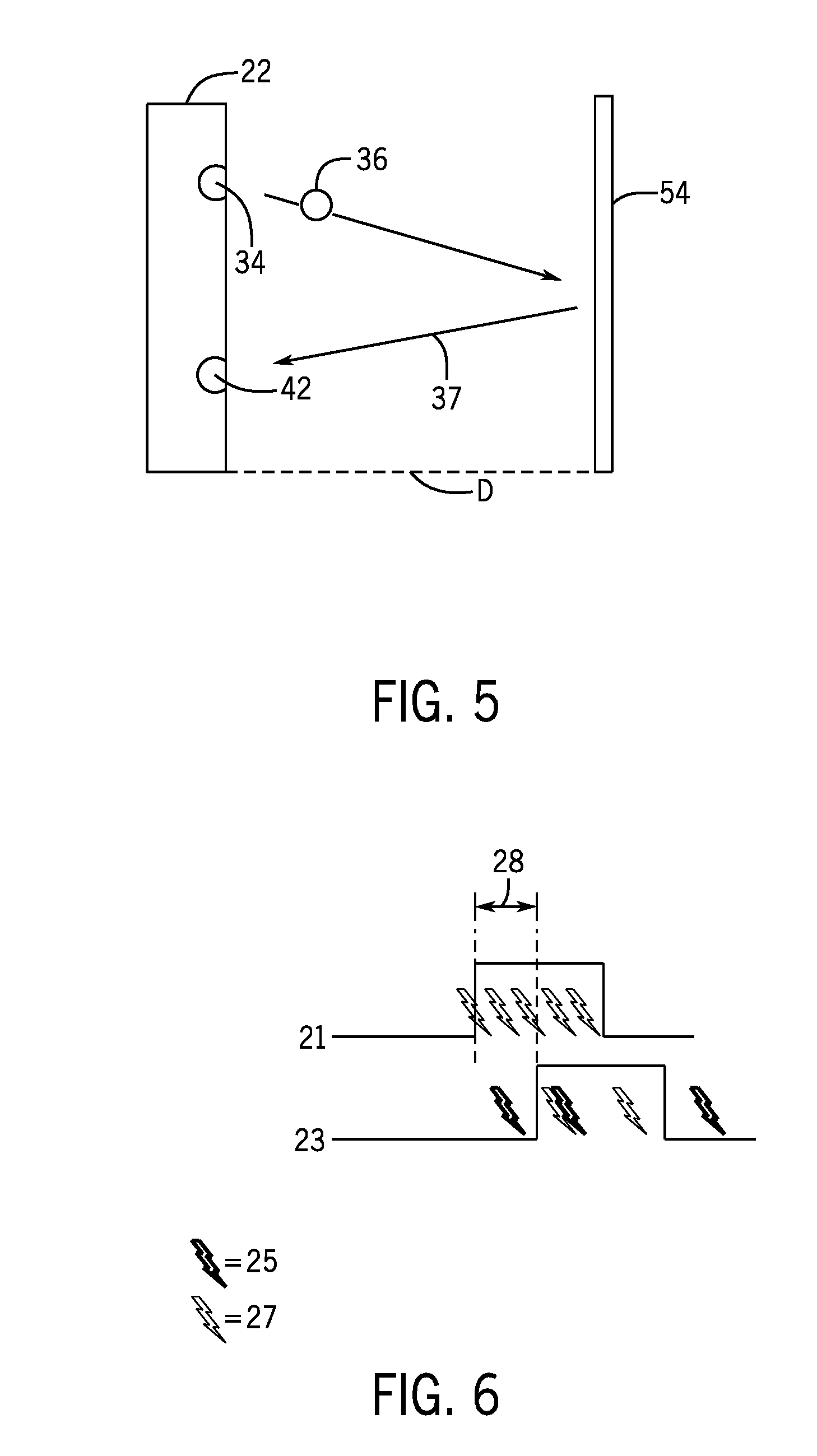
A recognition system for a bathroom fixture operates by sending a photon pulse from an emitter, monitoring for a presence of an object within a predefined detection zone, and operating the bathroom fixture if the distance of the object is within the predefined detection zone. The monitoring occurs by detecting photons with a sensor, establishing a correlated or uncorrelated state of the detected photons, optically filtering the detected photons, calculating a distance of the object from the sensor based on the photon pulse sent from the emitter and the returned photons collected at the sensor, and determining whether the distance of the object from the sensor falls within the predefined detection zone.

Description

CROSS-REFERENCE TO RELATED APPLICATIONS[0001]This application claims the benefit of U.S. Provisional Patent Application No. 62 / 206,036 filed Aug. 17, 2015, the contents of which are incorporated by reference herein in their entirety for all purposes.TECHNICAL FIELD[0002]This disclosure relates to recognition systems for bathroom fixtures. In particular, this disclosure relates to recognition systems for the accurate detection of an object within a pre-determined distance from a sensor for the purpose of selectively operating the fixture.BACKGROUND[0003]Infrared sensors have been used for detection or recognition systems in automated bathroom fixtures such as sink faucets, soap dispensers, and towel dispensers. Infrared sensors are active sensors that utilize low power detection and rely on the reflective properties of intended targets to accurately detect the presence of an object (for example, a user's hand).[0004]Typical infrared sensors suffer from at least three primary drawback...

Claims


Application Information

Patent Timeline
Patent Type & Authority Applications(United States)
IPC IPC(8): E03C1/05G05D7/06G01S7/486G01S17/10G01S17/88G01S17/04
CPCE03C1/057G01S17/10G05D7/0635G01S7/4865G01S17/88G01S7/497G01S17/04
Inventor MERCER, KEITH
Owner ZURN INDS
Learn More