Variable geometries fluid supply circuit for a turbomachine without volumetric pump

a fluid supply circuit and variable geometries technology, applied in the direction of machines/engines, efficient propulsion technologies, mechanical apparatus, etc., can solve the problems of substantial thermal heat dissipation and decrease in the overall performance of the turbomachine b>1/b>

Active Publication Date: 2017-02-23
SN DETUDE & DE CONSTR DE MOTEURS DAVIATION S N E C M A
View PDF6 Cites 6 Cited by
  • Summary
  • Abstract
  • Description
  • Claims
  • Application Information

AI Technical Summary

Benefits of technology

[0015]The plurality of centrifugal pumps is intended to further increase the pressure of the fluid that passes through them, while still limiting the encumbrance and the dissipation of thermal energy of the low-pressure pumping unit. The increase in the power supplied by the low-pressure pumping unit is in particular less substantial than the drop in the power supplied by the volumetric pump that results.
[0027]Moreover, using an electric volumetric pump makes it possible to limit the mass, the encumbrance and the power dissipated in the system for supplying. More precisely, the relatively low power supplied by the electric volumetric pump makes it possible to command it without adding to the turbomachine massive power electronics. Furthermore, the recirculation loop and the metering device can be suppressed from the system for supplying. Finally, it is possible to adjust the flow rate delivered by the electric volumic pump, in such a way as to limit the thermal losses associated with the circulation of an excess amount of fluid in the system for supplying.

Problems solved by technology

However, this excess fluid circulating in the recirculation loop of fluid 610 generates substantial thermal heat dissipation in the system for supplying 10.
This results in a decrease in the overall performance of a turbomachine 1 that comprises the system for supplying 10.

Method used


Image

  • Variable geometries fluid supply circuit for a turbomachine without volumetric pump
  • Variable geometries fluid supply circuit for a turbomachine without volumetric pump
  • Variable geometries fluid supply circuit for a turbomachine without volumetric pump

Examples


first embodiment

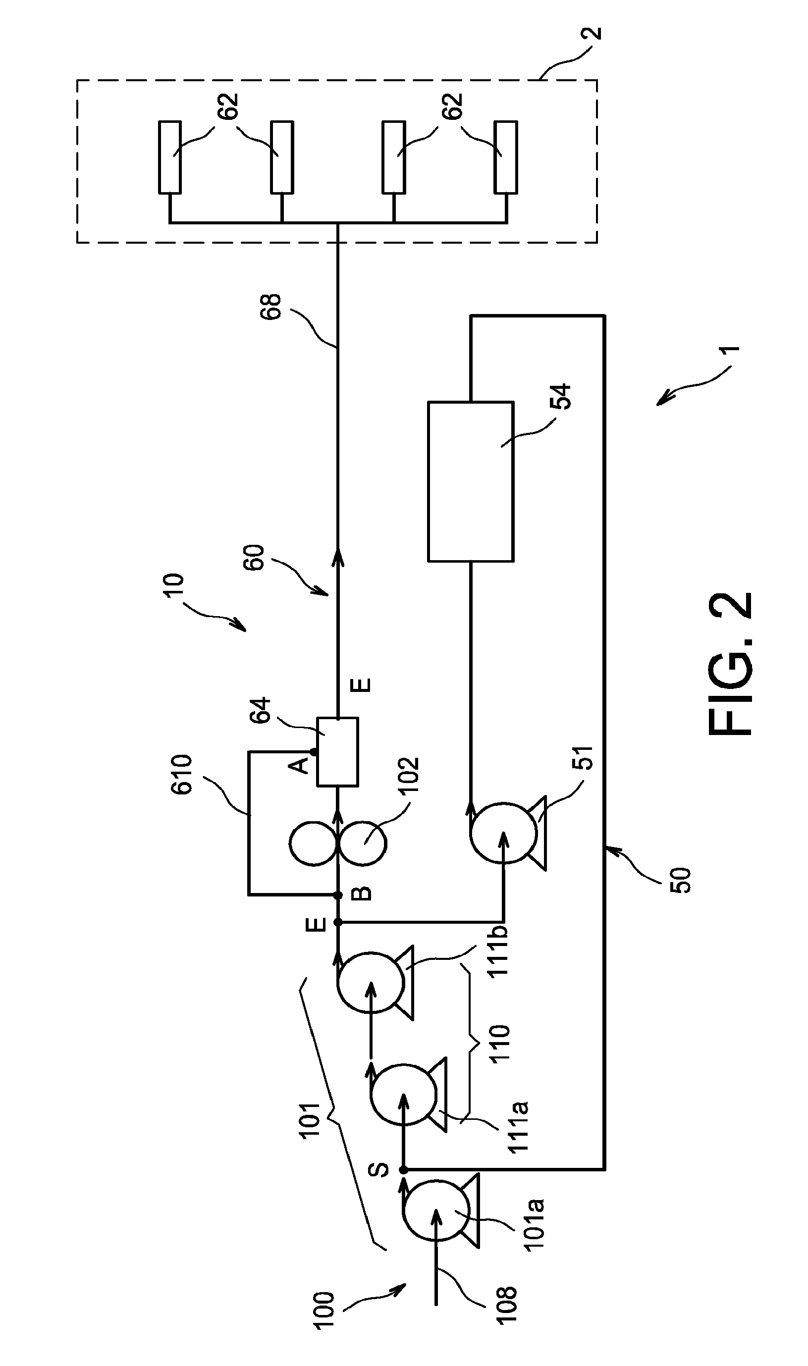
[0039]FIG. 2 is a partial diagrammatical view of a system for supplying a turbomachine with fluid, according to the invention;

second embodiment

[0040]FIG. 3 is a partial diagrammatical view of a system for supplying a turbomachine with fluid, according to the invention,

third embodiment

[0041]FIG. 4 is a partial diagrammatical view of a system for supplying a turbomachine with fluid, according to the invention.

DETAILED EXPOSURE OF PARTICULAR EMBODIMENTS

[0042]Identical, similar or equivalent parts of the various figures bear the same numerical references in such a way as to facilitate the passing from one figure to another.

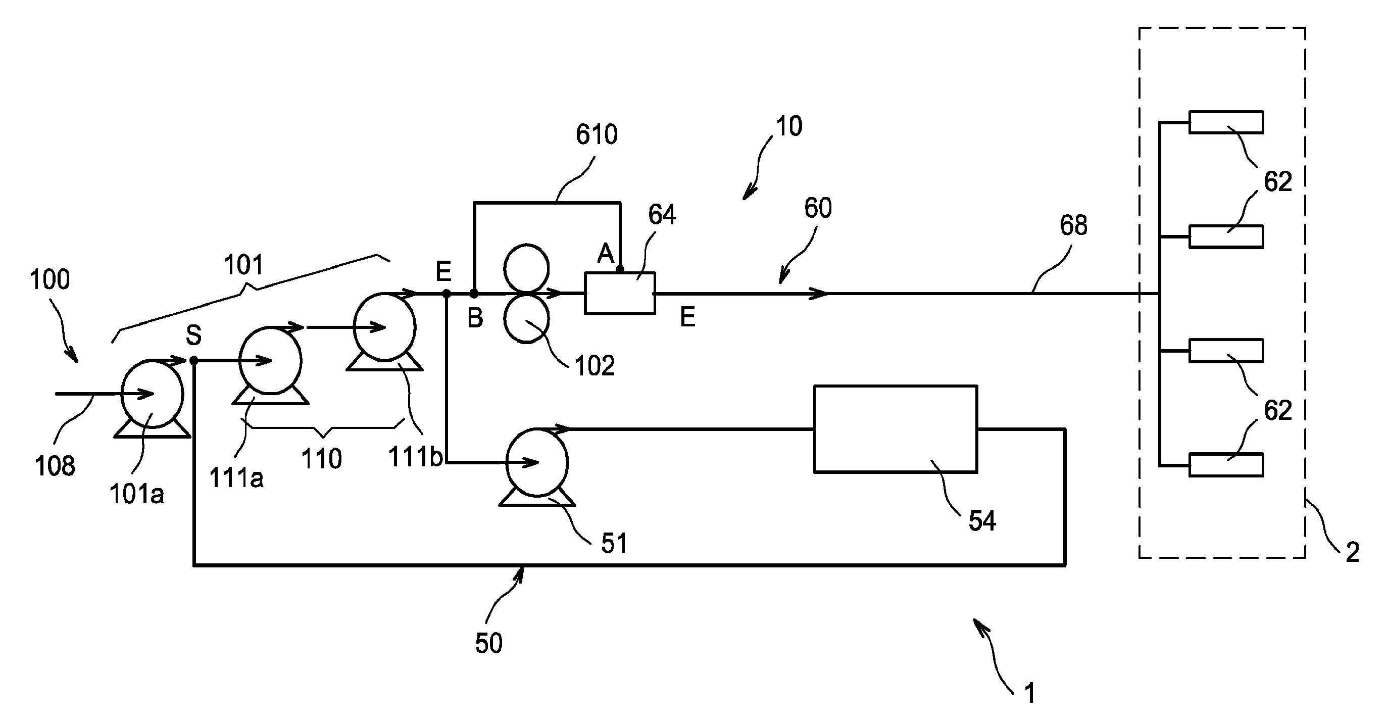
[0043]FIG. 2 shows a system for supplying 10 an aircraft turbomachine 1 with fluid. In the embodiment described, the fluid is fuel. However, when the turbomachine 1 comprises a differential gearbox (not shown) configured to drive in rotation at least one propeller, the fluid can also be lubricant, typically oil.

[0044]The turbomachine 1 comprises the system for supplying 10, one or several variable geometries 54 and a combustion chamber 2. These variable geometries 54 are equipment of the turbomachine 1 that require taking hydraulic power in order to operate. The variable geometries 54 can be of various natures, for example a cylinder, a servo valv...


PUM


Abstract

A system for supplying a turbomachine with fluid, the supply system including a low-pressure pumping unit intended to increase the pressure of the fluid flowing toward a downstream circuit. The downstream circuit divides at an inlet node, situated between the low-pressure pumping unit and the high-pressure volumetric pump, into a circuit supplying an injection system and a variable geometries supply circuit. The circuit supplying the injection system includes a high-pressure volumetric pump. The variable geometries supply circuit is configured to convey the fluid toward variable geometry from the inlet node to an outlet node connecting the variable geometries supply circuit to the upstream circuit between two pumps of the low-pressure pumping unit.

Description

TECHNICAL FIELD[0001]The invention relates to the general technical field of systems for supplying a turbomachine with fluid, in particular with lubricant or with fuel. More precisely, the invention relates to a system for supplying with fluid a combustion chamber of a turbomachine as well as a variable geometries turbomachine.PRIOR ART[0002]FIG. 1 shows a system for supplying 10 a turbomachine 1 with fuel, according to a known design of prior art. The system for supplying 1 comprises a low-pressure pump 11 configured to increase the pressure of the fuel flowing toward a hydraulic resistance 104. The low-pressure pump 11 is in particular a centrifugal pump. The fluid downstream of the low-pressure pump 11 then flows in the direction of a high-pressure volumetric pump 102.[0003]The high-pressure volumetric pump 102 is intended to supply with fluid at a constant flow rate a variable geometries 54 supply circuit 50 as well as a fuel supply circuit 60 of a combustion chamber 2.[0004]The...

Claims


Application Information

Patent Timeline
Patent Type & Authority Applications(United States)
IPC IPC(8): F02C7/06F02C7/236
CPCF02C7/06F05D2260/40311F05D2270/52F02C7/236F05D2260/406Y02T50/60F01D25/22F02C9/36F02C7/36F01D25/20F02C9/263F02C7/222F02C7/22
Inventor CHALAUD, SEBASTIEN
Owner SN DETUDE & DE CONSTR DE MOTEURS DAVIATION S N E C M A
Why Eureka
Try Eureka