Optical member, production method therefor, window material, and fixture

a production method and optical member technology, applied in the direction of door/window protective devices, instruments, applications, etc., can solve the problems of insufficient durability of films, accelerated heat island effect, and only regular reflection of incident sunlight by the reflective layer, and achieve excellent durability

Inactive Publication Date: 2017-02-23
DEXERIALS CORP
View PDF5 Cites 14 Cited by
  • Summary
  • Abstract
  • Description
  • Claims
  • Application Information

AI Technical Summary

Benefits of technology

[0030]The present invention can solve the above-described various problems in the conventional art, achieve the above-mentioned object, and provide an optical member having excellent durability with a complex structure, and a production method of the optical member, as well as a window material and joinery both containing the optical member.

Problems solved by technology

However, the reflective layer can only regular-reflect incident sunlight, because the reflective layer is typically disposed on planar glass.
In the city, therefore, the heat island effect is accelerated, and problems are caused, such as lawns do not grow only in the area where reflected light is applied.
However, the above-mentioned window films have a problem that durability of the films is insufficient due to the complicated structures.

Method used


Image

  • Optical member, production method therefor, window material, and fixture
  • Optical member, production method therefor, window material, and fixture
  • Optical member, production method therefor, window material, and fixture

Examples


first embodiment

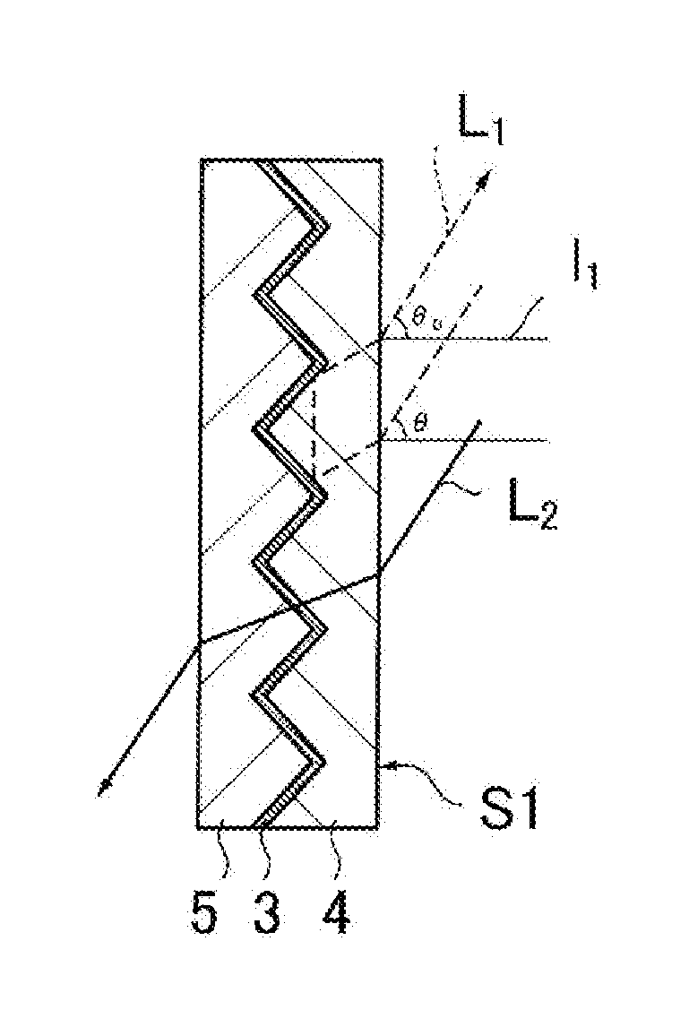
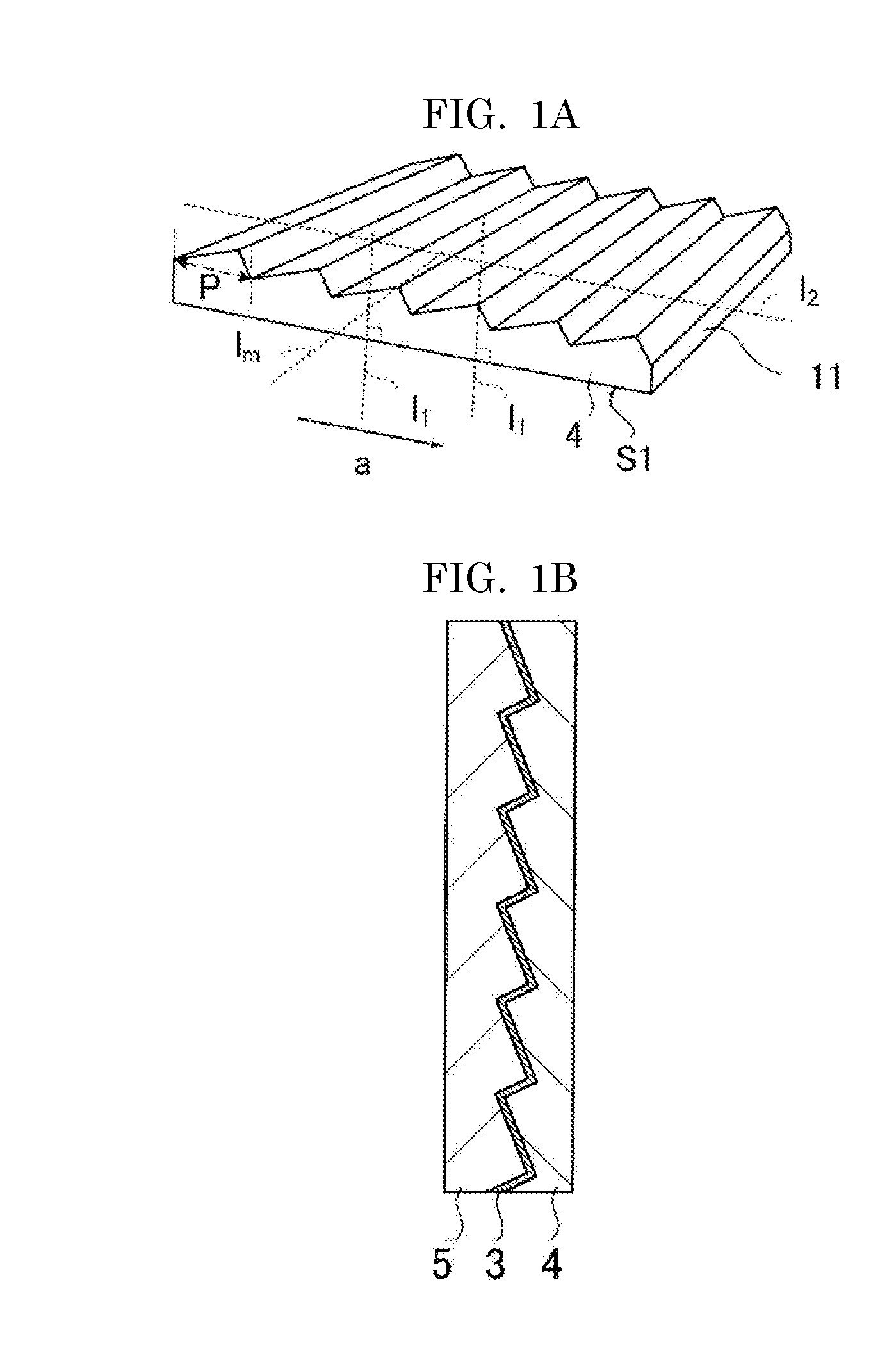
[0228]FIG. 14 is a cross-sectional view illustrating one structural example of the optical member according to the first embodiment of the present invention. As illustrated in FIG. 14, the optical member 1 includes an optical layer, and a reflective layer formed in an inner area of the optical layer. The optical member 1 has an incident surface S1 from which light, such as sunlight, enters, and a light-emitting surface S2 from which light passed through the first optical layer 4 is emitted out of the light entered from the incident surface S1.

[0229]FIG. 14 illustrates the example where the second optical layer 4 contains a pressure sensitive adhesive as a main component, and the optical member is bonded to a window material, etc. with the second optical layer 4. In the case where the optical member has the above-described structure, a difference in the refractive index between the pressure sensitive adhesive and the first optical layer is preferably within the above-mentioned range....

second embodiment

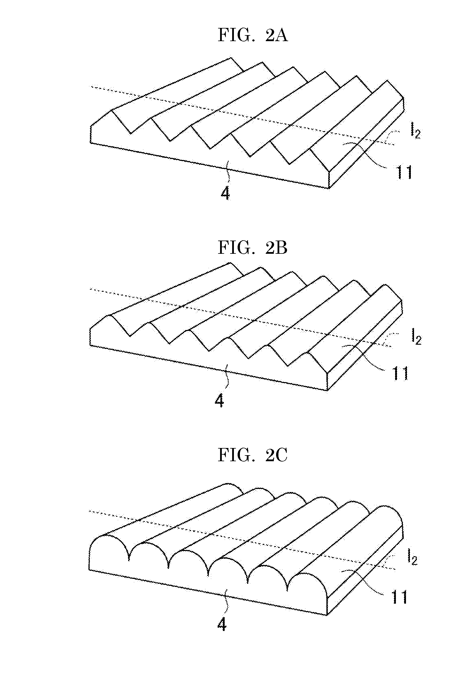
[0236]FIGS. 15 to 17 are cross-sectional views illustrating structural examples of structures of the optical member according to the second embodiment of the present invention. The second embodiment is different from the first embodiment in that the structures are two-dimensionally arranged on the main surface of the first optical layer 4.

[0237]On the main surface of the first optical layer 4, the structures 11 are two-dimensionally arranged. This arrangement is preferably an arrangement of the most densely packed state. For example, on a main surface of the first optical layer 4, a densely-packed array, such as a square densely-packed array, a delta densely-packed array, and a hexagon densely-packed array, are formed by two-dimensionally arrange the structures 11 in the most densely packed state. The square densely-packed array is an array obtained by arranging the structures 11 each having a square bottom surface in the square packed form. The delta densely-packed array is an arra...

third embodiment

[0239]FIG. 18 is a cross-sectional view illustrating one structural example of the optical member according to the third embodiment of the present invention. As illustrated in FIG. 18, the third embodiment is different from the first embodiment in that the optical member has beads 31 instead of the structures 11.

[0240]The beads 31 are embedded in a main surface of the base 4c in a manner that parts of the beads 31 are projected from the main surface, and the first optical layer 4 is formed with the base 4c and the beads 31.

[0241]A focal layer 32, a reflective layer 3, and a second optical layer 5 are sequentially laminated on the main surface of the first optical layer 4. For example, the beads 31 have spherical shapes. The beads 31 preferably have transparency. For example, the beads 31 have an inorganic material, such as glass, or an organic material, such as a polymer resin, as a main component.


PUM

PropertyMeasurementUnit
thicknessaaaaaaaaaa
optical refractive indexaaaaaaaaaa
lengthaaaaaaaaaa

Abstract

An optical member including a first optical layer having convex shapes, and a reflective layer, which is formed on the convex shapes of the first optical layer and is configured to reflect light including at least infrared light, wherein the reflective layer includes at least a metal layer, wherein a maximum height roughness Rz (nm) of inclined planes of the convex shapes is 3.0 times or less an average thickness (nm) of the metal layer, and wherein the average thickness of the metal layer is 40 nm or less.

Description

TECHNICAL FIELD[0001]The present invention relates to an optical member and a production method of the optical member, and a window material and joinery.BACKGROUND ART[0002]Recently, window films for shielding sunlight have been widely used for the purpose of reducing loads of air conditioning (see, for example, PTL 1). As window films for shielding sunlight, there are films that absorb sunlight and films that reflect sunlight.[0003]Regarding the films that reflect sunlight, techniques using an optical multi-layer film, a metal-containing film, or a transparent conductive film is used as a reflective layer have been already known (see, for example, PTL 2 to PTL 5). However, the reflective layer can only regular-reflect incident sunlight, because the reflective layer is typically disposed on planar glass. Therefore, the light emitted from the sky and regular-reflected by the reflective layer reaches another building outside or ground, and absorbed by the building or the ground to tra...

Claims


Application Information

Patent Timeline
Patent Type & Authority Applications(United States)
IPC IPC(8): G02B5/20E06B9/24B05D1/02G02B5/26C23C16/44B05D1/18B32B7/023
CPCG02B5/208C23C16/44B05D1/18E06B2009/2417G02B5/26E06B9/24B05D1/02C23C14/34B32B27/06B32B27/08B32B27/308B32B3/30E06B5/10B32B2255/10B32B2255/205B32B2255/28B32B2264/0214B32B2264/10B32B2264/101B32B2307/412B32B2307/416B32B2307/538B32B2307/754B32B2551/00B32B7/023E06B5/00G02B5/12
Inventor SAKUMA, RYOKOTANISHIMA, MASAYUKINAGAHAMA, TSUTOMU
Owner DEXERIALS CORP
Why Eureka
Try Eureka