
Phosphor wheel and wavelength converting device applying the same

a technology of phosphor wheel and wavelength converting device, which is applied in the direction of instruments, lighting and heating apparatus, optical elements, etc., can solve the problems of high power consumption of light sources of optical projectors, such as high-pressure mercury-vapor lamps, tungsten-halogen lamps, etc., and achieve the effect of correspondingly increasing the light emission efficiency of the phosphor wheel and high reflection efficiency

Inactive Publication Date: 2017-02-23
DELTA ELECTRONICS INC
View PDF19 Cites 17 Cited by
  • Summary
  • Abstract
  • Description
  • Claims
  • Application Information

AI Technical Summary

Benefits of technology

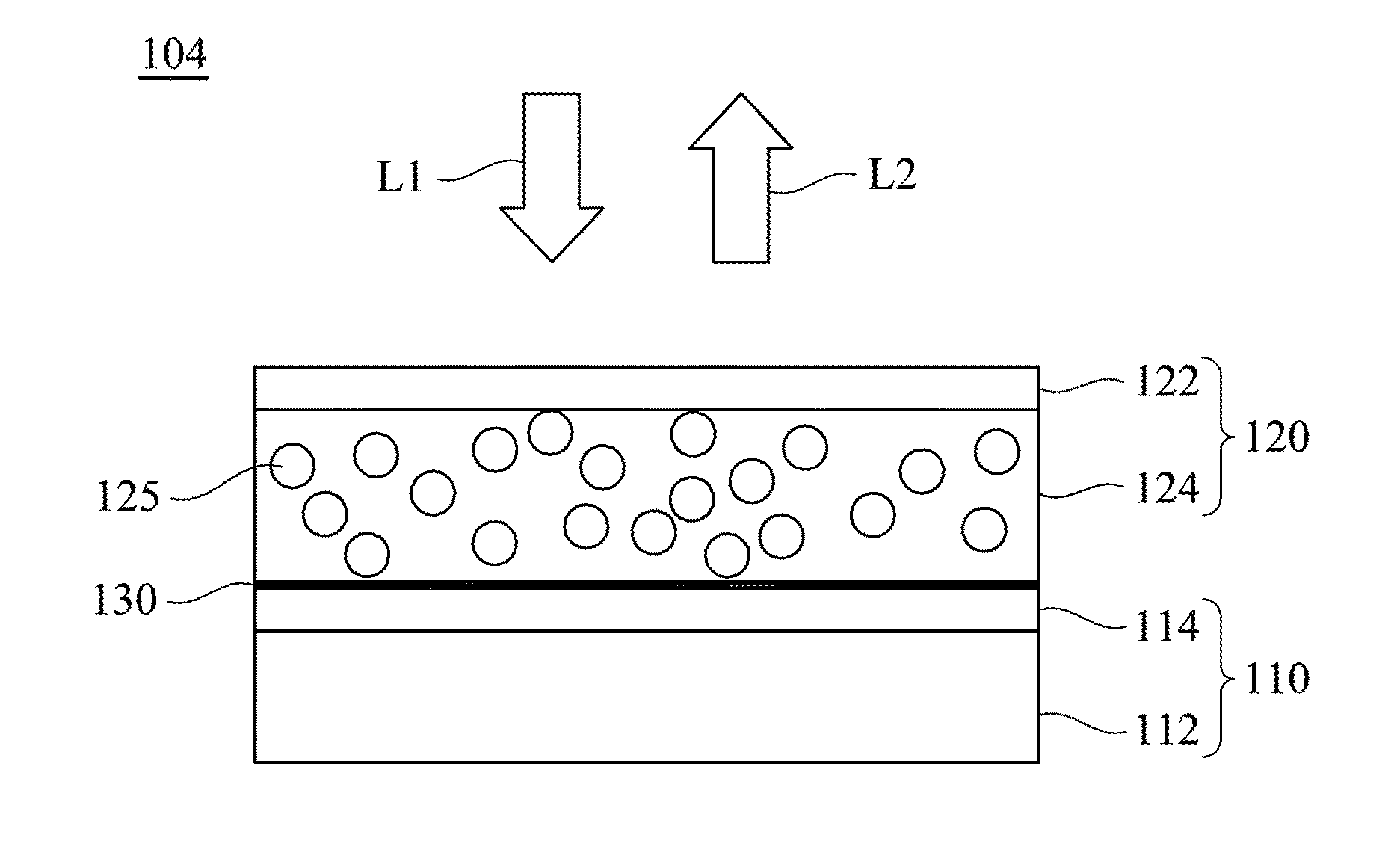
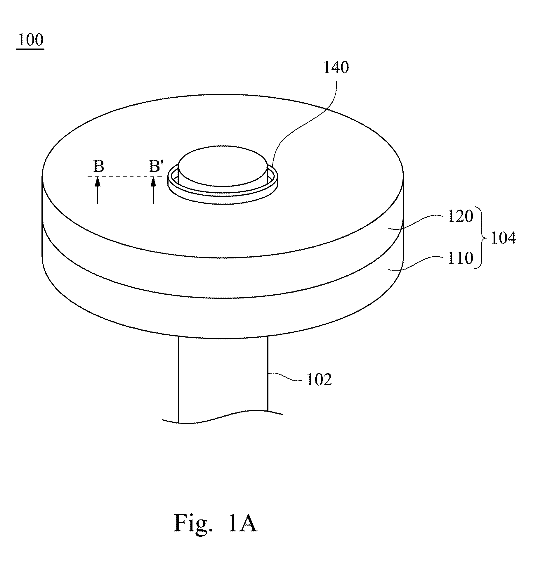
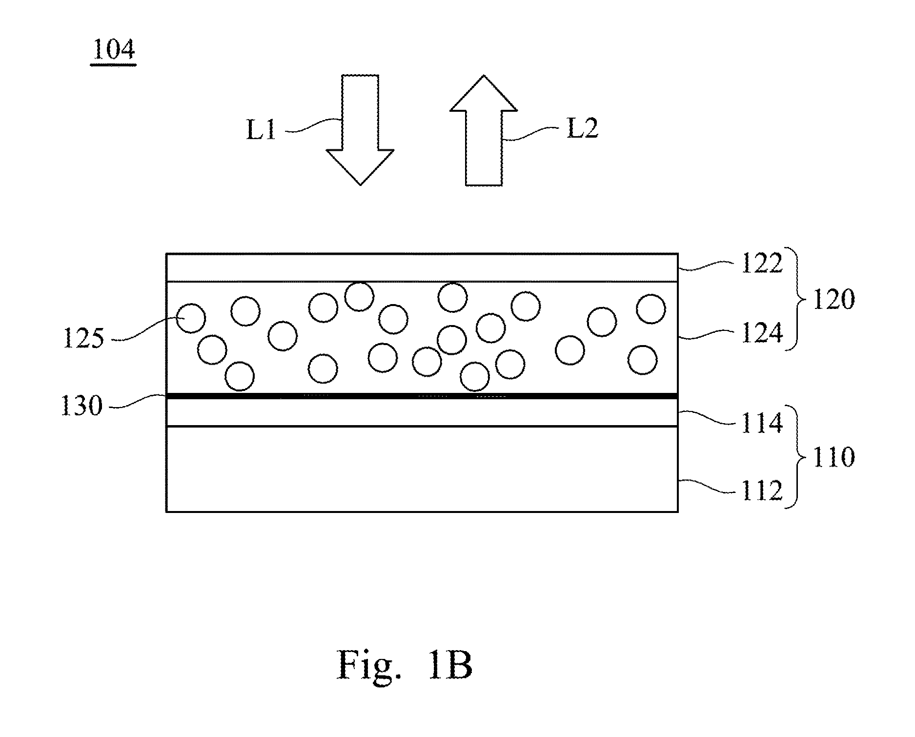
This patent describes a device that converts the wavelength of light beams. The device contains two optical units that are stacked and fixed together using a clamp. The space between the two units is filled with air, which improves the efficiency with which the light beams are reflected. This results in higher light emission efficiency from the device.

Problems solved by technology

Nowadays, light sources of the optical projectors, such as high-pressure mercury-vapor lamp, tungsten-halogen lamps, and metal-halogen lamps, are known to have high power consumption, with a short lifetime, as well they are bulky, and generate high heat.

Method used


Image

  • Phosphor wheel and wavelength converting device applying the same
  • Phosphor wheel and wavelength converting device applying the same
  • Phosphor wheel and wavelength converting device applying the same

Examples


Embodiment Construction

[0025]In the following detailed description, for purposes of explanation, numerous specific details are set forth in order to provide a thorough understanding of the disclosed embodiments. It will be apparent, however, that one or more embodiments may be practiced without these specific details. In other instances, well-known structures and devices are schematically shown in order to simplify the drawing.

[0026]It will be understood that, although the terms first, second, third etc. may be used herein to describe various elements, components, regions, layers and / or sections, these elements, components, regions, layers and / or sections should not be limited by these terms.

[0027]In order to increase a light emission efficiency of a phosphor wheel of a wavelength converting device, an aspect of the present disclosure provides a wavelength converting device including a first optical unit and a second optical unit. In a configuration of the wavelength converting device, the first optical u...


PUM

PropertyMeasurementUnit
transparentaaaaaaaaaa
sizeaaaaaaaaaa
wavelengthsaaaaaaaaaa

Abstract

A phosphor wheel includes a first optical unit, a second optical unit, and a clamping component. The first optical unit includes a substrate and an optical layer. The optical layer is disposed on the substrate. The second optical unit is stacked on the optical layer, in which the optical layer is configured to at least reflect light beams propagated from the second optical unit. The second optical unit includes a transparent substrate and a phosphor layer. The phosphor layer is disposed on the transparent substrate. The first optical unit and the second optical unit are fixed by the clamping component.

Description

RELATED APPLICATIONS[0001]This application claims priority to Taiwanese Application Serial Number 104127276, filed Aug. 21, 2015, which is herein incorporated by reference.BACKGROUND[0002]Technical Field[0003]The present disclosure relates to a phosphor wheel and a wavelength converting device applying the same[0004]Description of Related Art[0005]In recent years, optical projectors have been applied in many fields. The optical projectors have served an expanded range of purposes, for example, from use in consumer products to high-tech devices. Some kinds of optical projectors are widely used in schools, homes and business occasions in order to amplify image signals provided by an image signal source and then display on a projection screen. Nowadays, light sources of the optical projectors, such as high-pressure mercury-vapor lamp, tungsten-halogen lamps, and metal-halogen lamps, are known to have high power consumption, with a short lifetime, as well they are bulky, and generate hi...

Claims


Application Information

Patent Timeline
Patent Type & Authority Applications(United States)
IPC IPC(8): G02B26/00G03B21/20G02B1/11F21V13/08G02B27/14
CPCG02B26/008F21V13/08G03B21/204G02B1/11G02B27/141F21V7/26F21V9/32F21V9/38F21V9/40
Inventor CHOU, YEN-ICHEN, CHILU, CHUN-HSIEN
Owner DELTA ELECTRONICS INC
Learn More