
Stent With Mechanical Or Biological Heart Valve For Minimally Invasive Valve Replacement Procedure And Stent Application Device

a heart valve and mechanical or biological technology, applied in the field of stents, can solve the problems of low resistance of the sphere, structural fragility of the cage stem, and the need for permanent anticoagulant medicinal therapy for the patien

Inactive Publication Date: 2017-03-02
NEVES FILHO ANTONIO FRANCISCO
View PDF45 Cites 0 Cited by
  • Summary
  • Abstract
  • Description
  • Claims
  • Application Information

AI Technical Summary

Benefits of technology

This patent describes a device for heart valve replacement that includes a stent assembly and an application device. The stent has a unique shape that requires a specific application device to release it. The stent is attached to the application device and kept in a preserving solution. The stent is used to support a mechanical valve or a previously inserted heart valve during the surgical procedure. The stent has flaps that need to be positioned correctly in the heart valve, and a valve in the inner part of its tubular structure that allows blood flow only in one direction. The valve can be made of biological or mechanical materials, and may be compressed or fixed inside the stent during the surgical procedure. The stent can also be stored without the valve and fixed inside the stent during the surgery. The technical effects of this invention include improved stability and flexibility of the stent, simplified application procedure, and improved support for the heart valve during the surgical procedure.

Problems solved by technology

The surgical approach of mitral valve pathologies demands the application of annuloplasty rings for fixing the base, which is a relatively time-consuming procedure, since anchoring of fixing wires is needed.
The initial project envisaged numerous disadvantages, such as structural fragility of the cage stems, low resistance of the sphere (causing injury to the septa) and the need of a permanent anticoagulant medicinal therapy for the patient.
However, negative aspects remained, such as mechanical fatigue, use of anticoagulant medication and calcification of the heart valve.
One of the limitations inherent to this device is the impossibility of timely adjustment of chain dimensions.
Further, the exposure of fixing support elements facilitates contamination or even injury of cardiac muscles.

Method used


Image

  • Stent With Mechanical Or Biological Heart Valve For Minimally Invasive Valve Replacement Procedure And Stent Application Device
  • Stent With Mechanical Or Biological Heart Valve For Minimally Invasive Valve Replacement Procedure And Stent Application Device
  • Stent With Mechanical Or Biological Heart Valve For Minimally Invasive Valve Replacement Procedure And Stent Application Device

Examples


Embodiment Construction

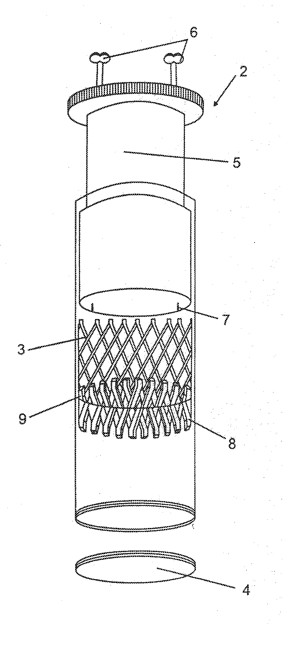
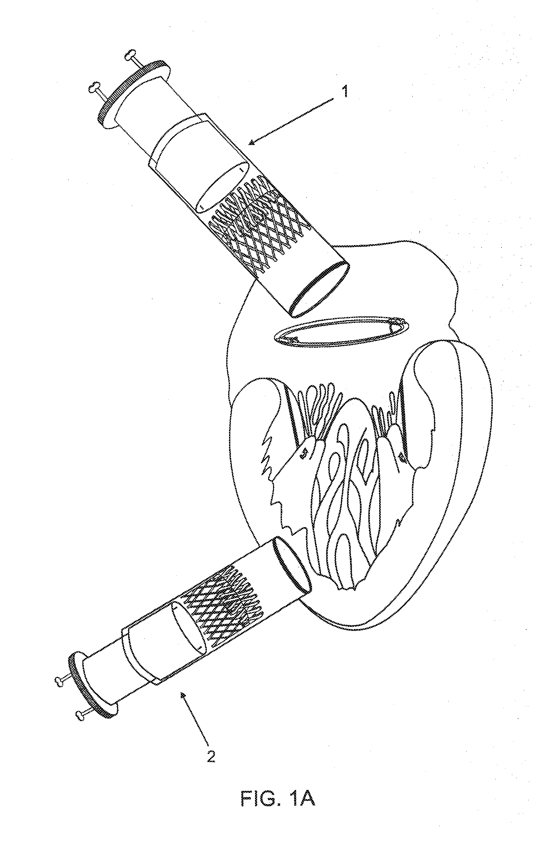
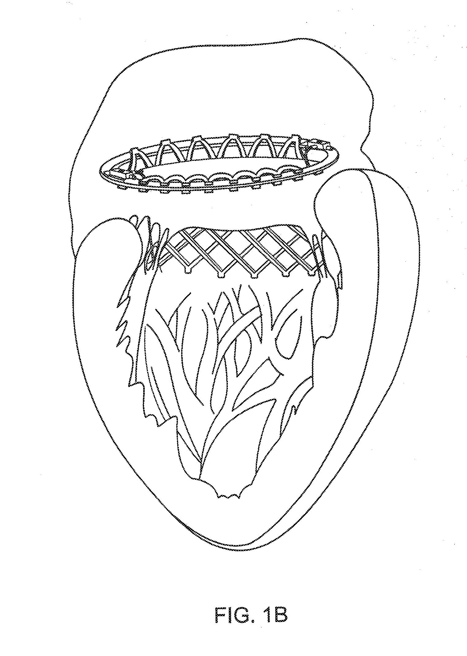
[0027]The device of this invention comprises a stent assembly for heart valve and application device thereof. The stent comprises a tubular structure with one of its ends including an upper flap (8) and a lower flap (9). When the stent (3) is released from the application device (1 or 2), the tubular structure expands, and the flaps are opened, fixing the stent (3) to the heart valve.

[0028]Due to its shape, the stent requires a specific application device (1 or 2) to be used. The application device (1 or 2) features a plunger (5) with two screws (6) that pierce through it. The adjustments of the screws (6), in one of the ends, are located on the outer part of the application device (1 or 2) and the threaded end (7) is on the inner part of the application device. In the threaded part (7), the stent (3) is attached and kept inside the application device, as seen in FIG. 2C. Preferably, the application device must have an anatomical shape, which facilitates intra-arterial movement unti...


PUM


Abstract

A cardiac stent assembly featuring support flaps for a heart valve replacement procedure, while being able to place a mechanical or biological valve in an adapter fixed on the inner part of a stent body of the stent assembly. The stent assembly can be placed within heart valves sustained on an annular or ovoid mechanical support ring. For the positioning procedure of the stent assembly in the valve, an application device can be used wherein the stent body is inside the application device so that is possible to assemble and keep the entire stent assembly ready for use.

Description

[0001]This invention patent application discloses a cardiac stent with a mechanism for positioning the mechanical or biological valve to be used during heart valve replacement or procedure, as well as a stent application device thereof. The stent has a tubular shape made of grated material with two flaps, with the heart valve fixed within. The application device comprises a syringe inside which the stent is placed, said syringe comprising a threaded cap that allows storage of the stent in a solution for conservation. Two screws pierce through the plunger of the syringe and fix the stent structure.DESCRIPTION OF THE STATE OF THE ART[0002]The state of the art features a variety of devices for heart valve replacement, especially, by stents. Some of these stents feature an application device, specifically designed for the positioning procedure.[0003]The surgical approach of mitral valve pathologies demands the application of annuloplasty rings for fixing the base, which is a relatively ...

Claims


Application Information

Patent Timeline
Patent Type & Authority Applications(United States)
IPC IPC(8): A61F2/24
CPCA61F2/2418A61F2230/008A61F2/2436A61F2/2409A61F2/24A61F2/90A61F2/95A61F2/848A61F2/0095A61F2/2403A61F2220/0016A61F2250/006A61F2230/0052A61F2230/0078A61F2/2445
Inventor NEVES FILHO, ANTONIO FRANCISCO
Owner NEVES FILHO ANTONIO FRANCISCO
Learn More