Crossbar spinal prosthesis having a modular design and systems for treating spinal pathologies

a spinal pathology and modular technology, applied in the field of spinal pathology devices and surgical methods, can solve the problems that current prosthesis designs do not provide prosthesis systems, and achieve the effect of improving tissue shielding capabilities and reducing the occurrence of tissue being caugh

Active Publication Date: 2017-03-02
GLOBUS MEDICAL INC
View PDF24 Cites 19 Cited by
  • Summary
  • Abstract
  • Description
  • Claims
  • Application Information

AI Technical Summary

Benefits of technology

[0028]In yet another embodiment, there is provided a crossbar that is adaptable and configured for placement joining two cephalad elements, or alternatively, two caudal elements. Additional crossbar embodiments provide different attachment mechanisms and locations between the elements. Moreover, additional embodiments provide adaptability of one or more cephalad elements, one or more caudal elements and / or one or more crossbar elements.
[0036]In additional alternative embodiments, there are provided different components, methods and configurations to provide improved tissue shielding capabilities, such as for example, basing the selection of the modular components on reducing the occurrence of tissue being caught in the prosthesis. In one specific embodiment, the relative positions are modified such as by reversing the caudal and the cephalad bearings to protect tissue from getting caught in the contacting arms.

Problems solved by technology

Prosthesis customization to patient specific disease state and anatomy are among the challenges faced when implanting a prosthesis.
Current prostheses designs have not provided prosthesis systems having modular designs that are configurable and adaptable to patient specific disease state and anatomy.

Method used


Image

  • Crossbar spinal prosthesis having a modular design and systems for treating spinal pathologies
  • Crossbar spinal prosthesis having a modular design and systems for treating spinal pathologies
  • Crossbar spinal prosthesis having a modular design and systems for treating spinal pathologies

Examples


first embodiment

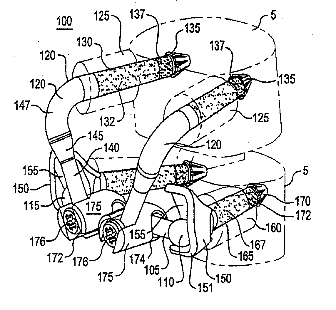
[0103]The crossbar 105, in a first embodiment, has a first end 110 and a second end 115. In the illustrated embodiment the crossbar 105 is a two piece bar where the first end 110 is attached to a threaded male portion 104 having threads 109. The crossbar second end 115 is attached to a threaded female portion 106 sized to receive the threads 109. As will be described in greater detail below, the threaded ends allow for the width of the crossbar to be adjusted to mate with the width between caudal bearings 150 (FIG. 9). Additional alternative embodiments of the crossbar 105 could include a series of solid crossbars of varying widths and / or thicknesses (See FIGS. 9A, 9B and 9C), or an adjustable crossbar having some form of locking or biasing mechanism (such as a spring-loaded tensioner or detent mechanism, etc.).

[0104]A pair of cephalad prosthesis elements 120 are also illustrated in the exemplary embodiment of the configurable and adaptable spinal prosthesis 100 of the present inven...

embodiment 330

[0220]FIG. 31C illustrates an embodiment of an adaptive spinal prosthesis 300C having a crossbar embodiment 330 and crossbar locks 331. A crossbar lock 331 includes a cephalad arm clamp 334 about a cephalad arm 145 and a crossbar clamp 336 that encircles the crossbar 330. A dual clamp housing 332 and fastener 338 join the clamps 334, 336. The width of crossbar 330 is determined by moving the crossbar 330 relative to the crossbar clamps 336. The crossbar spacing between a cephalad bearing 305 and an elbow 147 is determined by moving the cephalad arm clamp 334 along the cephalad arm 147 to the desired position. Once the width of crossbar 330 and the position of the crossbar 330 relative to the bearing 305 and the elbow 147 are selected, the crossbar 330 is secured into the selected position by tightening the fastener 338. Tightening fastener 338 results in articulation within dual clamp housing 332 to tighten both the arm clamp 334 about the cephalad arm 145 and the crossbar clamp 336...

embodiment 340

[0221]FIG. 31D illustrates an embodiment of an adaptive spinal prosthesis 300D having a crossbar embodiment 340 with crossbar locks 341. A crossbar lock 341 includes a cephalad arm clamp 342, a crossbar clamp 344 and a fastener 346. The position of the crossbar 340 between the cephalad bearing 305 and the elbow 147 is changed by sliding the arm clamps 342 along the cephalad arms 147. The crossbar width between the crossbar clamps 344 is adjusted by sliding the crossbar 344 relative to the clamps 344. Once the position of the crossbar 340 between the cephalad bearing 305 and the elbow 147 and the width of the crossbar 340 are selected, the crossbar position is secured by tightening fastener 346. Tightening fastener 346 urges the arm clamp 342 about the cephalad arm 145 and the crossbar clamp 344 about the crossbar 340. In the illustrated embodiment, the crossbar 340 is contained in a plane above a plane that contains the cephalad arms 145, though it could be even with or below the pl...


PUM


Abstract

An adaptable spinal facet joint prosthesis may include a pedicle fixation element; a laminar fixation element; and a facet joint bearing surface having a location adaptable with respect at least one of the pedicle fixation element and the laminar fixation element. Methods of implanting an adaptable spinal facet joint prosthesis may include determining a desired position for a facet joint bearing surface; and attaching a prosthesis comprising a facet joint bearing surface to a pedicle portion of a vertebra and a lamina portion of a vertebra to place the facet joint bearing surface in the desired position. A facet joint prosthesis implant tool may include a tool guide adapted to guide a vertebra cutting tool; and first and second fixation hole alignment elements extending from the saw guide. Systems for treating spinal pathologies may include intervertebral discs in combination with spinal and facet joint prostheses.

Description

CROSS-REFERENCE TO RELATED APPLICATION[0001]This application is a continuation of U.S. patent application Ser. No. 11 / 577,964, filed Apr. 25, 2007, which is a continuation of PCT application No. PCT / US2005 / 038335, filed Oct. 24, 2005. This application is also a continuation-in-part of U.S. application Ser. No. 14 / 633,722, filed Feb. 27, 2015, which is a continuation of U.S. patent application Ser. No. 13 / 847,746, filed Mar. 20, 2013, now U.S. Pat. No. 8,992,574, which is a continuation of U.S. patent application Ser. No. 11 / 948,994, filed Nov. 30, 2007, now U.S. Pat. No. 8,425,557, which is a continuation of U.S. patent application Ser. No. 10 / 973,939, filed Oct. 25, 2004, now abandoned, which is a continuation-in-part of U.S. application Ser. No. 10 / 831,657, filed Apr. 22, 2004, now U.S. Pat. No. 8,187,303. This application is also a continuation-in-part of U.S. patent application Ser. No. 14 / 619,574, filed Feb. 11, 2015, which is a continuation of U.S. patent application Ser. No. ...

Claims


Application Information

Patent Timeline
Patent Type & Authority Applications(United States)
IPC IPC(8): A61F2/44A61B17/15A61B17/58A61B17/70A61F2/00A61F2/02A61F2/30A61F2/46
CPCA61F2/4405A61F2002/30331A61F2002/30537A61F2002/30616A61F2002/3008A61B17/15A61F2/442A61F2002/30538A61F2002/3055A61B17/7064A61F2/30742A61F2/4455A61F2002/30405A61F2002/30462A61F2002/30507A61F2002/30563A61F2002/30566A61F2002/30601A61F2002/30604A61F2002/30607A61F2002/30617A61F2002/30682A61F2002/3069A61F2002/30841A61F2002/3085A61F2002/30878A61F2002/30884A61F2002/4631A61F2220/0025A61F2220/0033A61F2220/0075A61F2250/0004A61F2250/0006A61F2250/0007A61F2250/0062A61F2250/0097A61B90/39
Inventor KUIPER, MARK K.YAGER, DAVIDTOKISH, JR., LEONARDROSLER, DAVID MICHAELREILEY, MARK A.FUNK, MICHAEL J.OCHOA, JORGE A.ROGERS, SUSAN L.RALPH, CHRISTOPHER R.CHARBONNEAU, MARK T.BROMAN, RICHARD J.MCLEER, THOMAS J.
Owner GLOBUS MEDICAL INC
Why Eureka
Try Eureka