Integrated access floor system

a technology of access flooring and composite trusses, which is applied in the direction of space heating and ventilation, lighting and heating apparatus, heating types, etc., can solve the problems of system not integrating access flooring into the top slab of composite trusses, and the limitations of the diaphragm construction method

Inactive Publication Date: 2017-03-02
CLARK PACIFIC PRECAST LLC
View PDF44 Cites 17 Cited by
  • Summary
  • Abstract
  • Description
  • Claims
  • Application Information

AI Technical Summary

Benefits of technology

[0023]The invention comprises a prefabricated integrated access deck panel having a bottom flange, one or more structural webs, and an optional top flange. The bottom flange acts as a ceiling soffit for the floor below, and may be cast with custom recesses or decorative patterns on its lower side to accommodate lighting or architectural features. The bottom flange may also be cast with circuits of radiant tubing passing through it, for heating or cooling.

Problems solved by technology

Historically, pretopped diaphragm construction methods have been limited to buildings not located within a region having high seismic activity.
This system does not integrate access flooring into the top slab of the composite truss.

Method used


Image

  • Integrated access floor system
  • Integrated access floor system
  • Integrated access floor system

Examples


Embodiment Construction

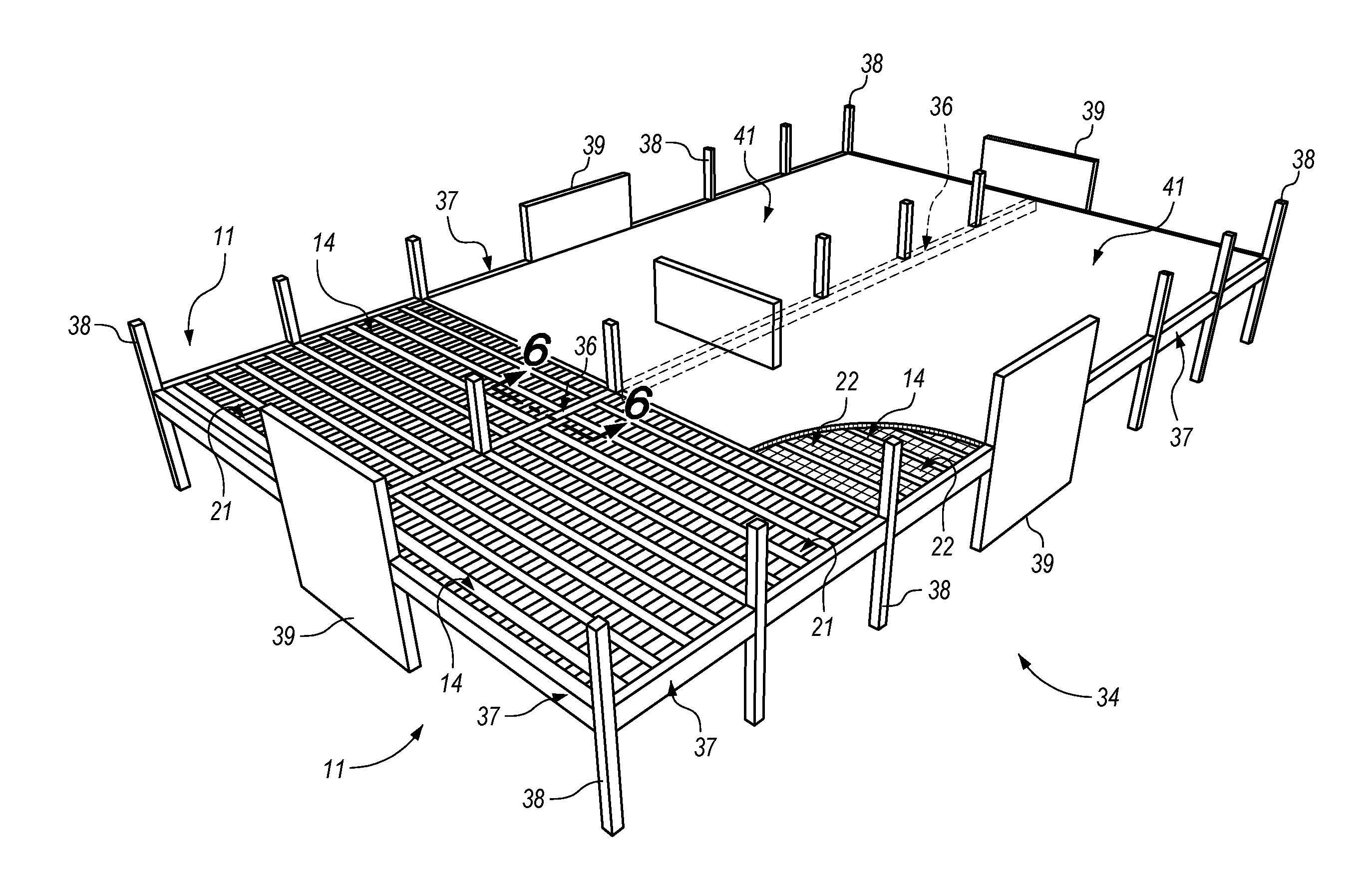
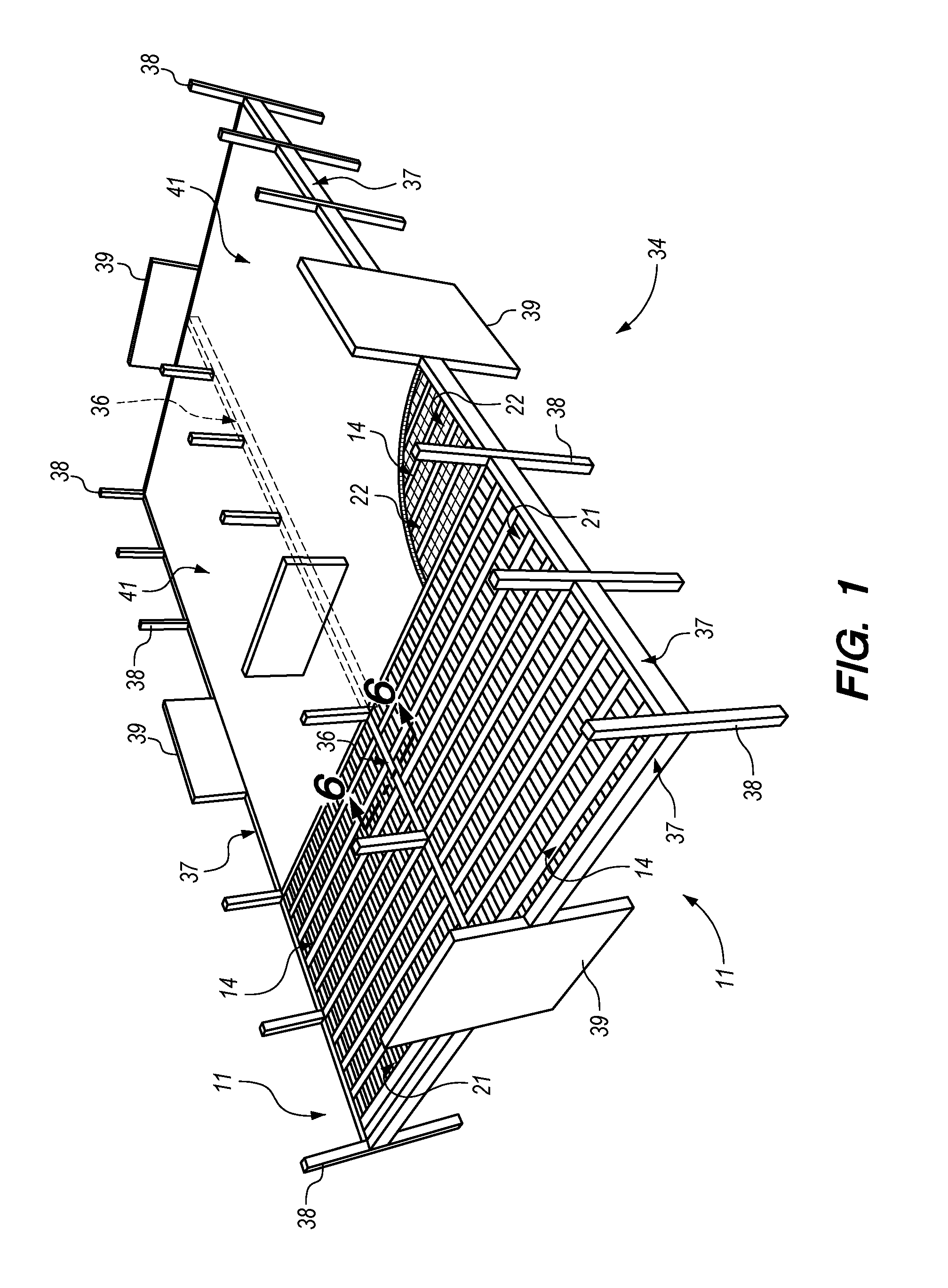
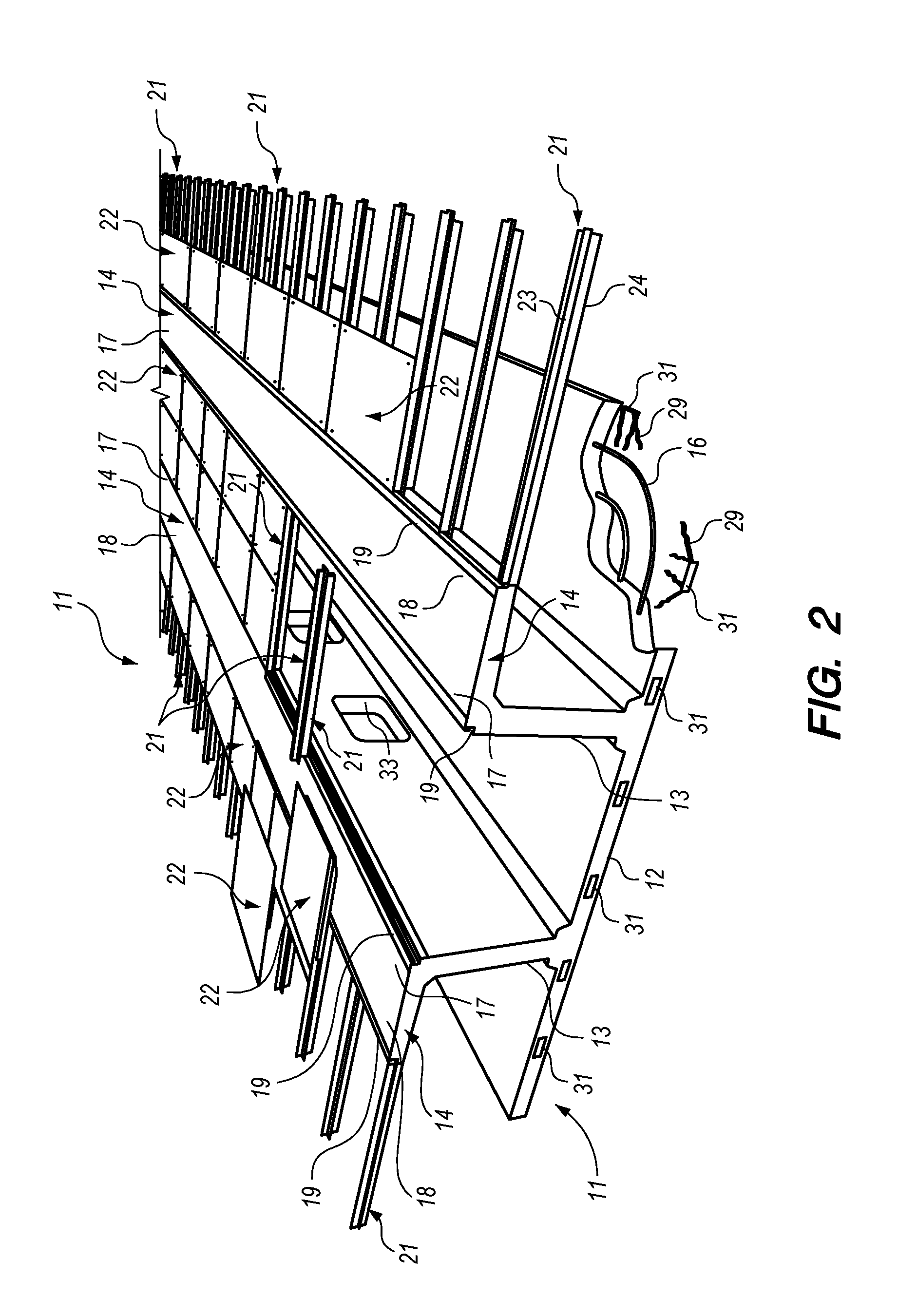
[0046]Turning now to the drawings, and in particular FIGS. 1 and 2, an integrated access deck panel 11 is shown. Preferably deck panels 11 are manufactured at a facility off-site from a main building site. At the manufacturing facility, individual panels 11 are pre-cast from concrete into an integrated structure, including whatever customized structural or architectural features are called for. After the panels 11 have cured, they are transported to the building site where they can be assembled and joined with other building structures and assemblies. This manner of construction, involving prefabrication of major structural components off-site, has been proven to save labor costs and to accelerate construction speed, compared to conventional methods of construction.

[0047]The access deck panel 11 includes a bottom flange 12, one or more structural webs 13, and an optional top flange 14. The bottom flange 12 acts as a ceiling soffit for the floor below, and its underside may include d...


PUM


Abstract

A prefabricated integrated access deck panel includes a bottom flange, one or more structural webs, and an optional top flange. The bottom flange acts as a ceiling soffit, and may include radiant tubing for heating or cooling. The top flange, when present, acts as the floor surface and also supports components of the access floor system. Alternatively, only support rails are used to secure the removable and reconfigurable access floor panels. The webs includes apertures to allow the passage of air and components of the building's electrical, communication, water, and mechanical systems. Individual deck panels may either be directly interconnected to each other or joined by a common beam to form a diaphragm. Alternative embodiments are disclosed including different deck panel connection and support arrangements, different numbers and configurations for the webs and flanges, and single and dual plenum constructions.

Description

PRIORITY CLAIM[0001]Pursuant to the provisions of 35 U.S.C. Section 119(e), Applicants claim the priority of their U.S. Provisional Patent Application No. 62 / 211,758, filed Aug. 29, 2015.BACKGROUND OF THE INVENTION[0002]1. Field of the Invention[0003]The invention relates generally to structural floor systems employed in the construction of reinforced concrete, precast concrete, and structural steel buildings. More specifically, the invention pertains to a structural floor system comprising a precast concrete deck integrating a mechanical plenum with an access floor having free air movement capabilities.[0004]2. Description of the Prior Art[0005]A building structure in its most basic form is a series of structural elements designed and arranged to support vertical loads. Vertical loads, such as the weight of the building and the items and occupants in the building, are any forces acting on the building that are the direct result of gravity. Vertical loads are transferred through flo...

Claims


Application Information

Patent Timeline
Patent Type & Authority Applications(United States)
IPC IPC(8): E04B5/48E04B1/19F24F5/00E04B5/44E04B5/02F24D3/14E04F15/02E04B1/00
CPCE04B5/48E04F15/02183E04B1/19F24F5/0089E04B5/44E04B5/02F24D3/14E04B1/003E04B5/04E04B5/43Y02B30/00
Inventor MOHLE, JON F.ROBISON, MARK L.
Owner CLARK PACIFIC PRECAST LLC
Why Eureka
Try Eureka