
High damping low force hydraulic strut tensioner

a hydraulic strut and high damping technology, applied in the direction of belt/chain/gearing, mechanical equipment, belts/chains/gearings, etc., can solve the problems of reducing prone to binding or stiction, and difficult to keep the plunger concentric, so as to achieve less damping force, increase the effective hydraulic clearance, and reduce the effect of damping

Active Publication Date: 2017-03-02
GM GLOBAL TECH OPERATIONS LLC
View PDF4 Cites 2 Cited by
  • Summary
  • Abstract
  • Description
  • Claims
  • Application Information

AI Technical Summary

Benefits of technology

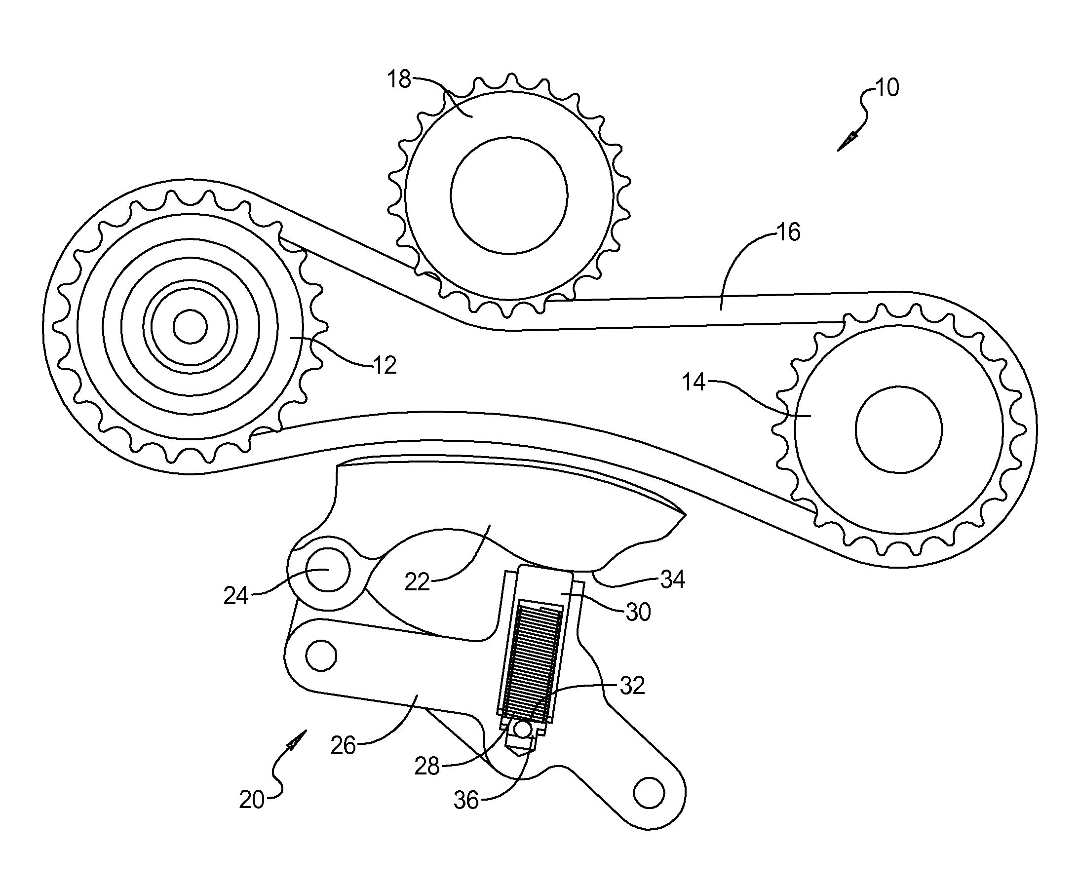
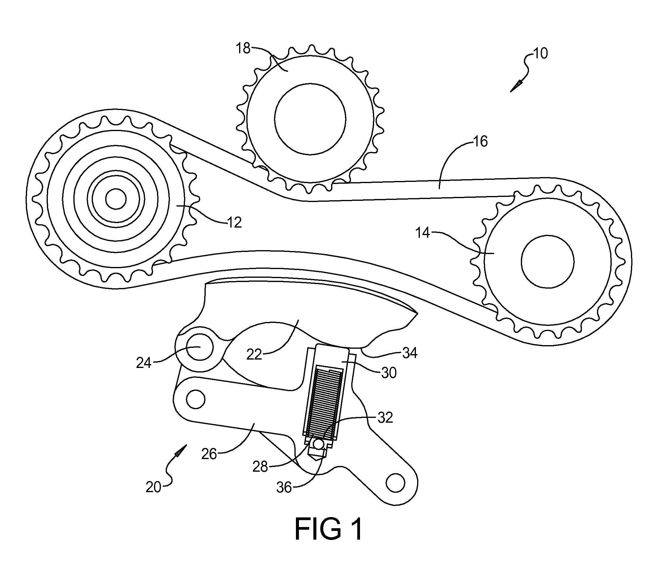
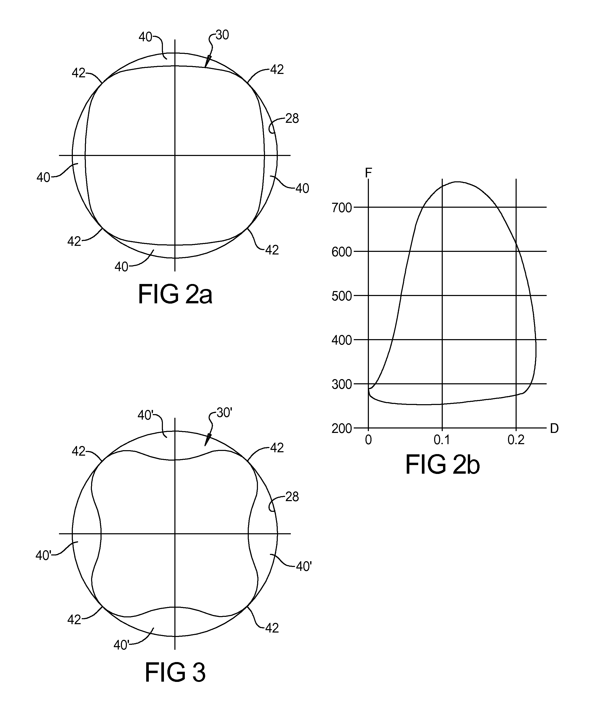
This patent is for a hydraulic chain or belt tensioner that uses a plunger with a non-standard shape to minimize the space between the plunger and the cylindrical hole, while increasing the effective hydraulic clearance to provide higher damping with less force. A spring maintains a biasing force against the plunger while the pressurized oil within the cavity dampens the movement of the plunger to prevent rattling or slipping. The plunger has a non-standard profile that creates high concentricity with the cylindrical hole, and enhanced hydraulic clearance areas between the plunger and the hole increase the effective hydraulic diameter to achieve higher flow with less force.

Problems solved by technology

The high clearance makes it difficult to keep the plunger concentric with the bore during operation, which makes it prone to binding or stiction (tendency to bind or stick due to friction).

Method used


Image

  • High damping low force hydraulic strut tensioner
  • High damping low force hydraulic strut tensioner
  • High damping low force hydraulic strut tensioner

Examples


Embodiment Construction

[0014]Example embodiments will now be described more fully with reference to the accompanying drawings.

[0015]Example embodiments are provided so that this disclosure will be thorough, and will fully convey the scope to those who are skilled in the art. Numerous specific details are set forth such as examples of specific components, devices, and methods, to provide a thorough understanding of embodiments of the present disclosure. It will be apparent to those skilled in the art that specific details need not be employed, that example embodiments may be embodied in many different forms and that neither should be construed to limit the scope of the disclosure. In some example embodiments, well-known processes, well-known device structures, and well-known technologies are not described in detail.

[0016]The terminology used herein is for the purpose of describing particular example embodiments only and is not intended to be limiting. As used herein, the singular forms “a,”“an,” and “the” ...


PUM


Abstract

A tensioner device, includes a housing defining a cylindrical bore. A plunger is disposed in the bore and has a non-cylindrical outer surface. A spring is engaged with the plunger for biasing the plunger in an outward direction and an oil passage is in communication with the cylindrical bore for delivering pressurized oil to the bore. The non-cylindrical outer surface provides hydraulic clearance areas between the plunger and the bore to provide improved damping without high damping force.

Description

FIELD[0001]The present disclosure relates to a hydraulic belt or chain tensioner with improved damping performance.BACKGROUND AND SUMMARY[0002]This section provides background information related to the present disclosure which is not necessarily prior art.[0003]Hydraulic tensioners are used for applying tension against a chain or belt for preventing chain rattle or belt slippage in an auxiliary drive system of an engine or in other industrial machines. In a typical hydraulic tensioner as illustrated in FIG. 4a, a cylindrical plunger 100 is disposed within a cylindrical bore 102 of a housing and is biased against a tensioner shoe for applying a tension force against a belt or chain. A high pressure oil is introduced into the bore 102 for damping movement of the plunger. The oil is forced from the high-pressure chamber where it passes through a clearance 104 around the plunger 100 and into the chain cavity. Typically, to create high amounts of damping without high damping force, a hy...

Claims


Application Information

Patent Timeline
Patent Type & Authority Applications(United States)
IPC IPC(8): F16H7/08F16H7/02F16H7/06
CPCF16H7/0838F16H7/06F16H2007/0893F16H2007/0812F16H2007/0872F16H7/02F15B15/1419F16H7/08F16H7/0829F16H2007/0806F16H2007/0814F16H2007/0859
Inventor STALEY, ERIC D.STALEY, DAVID R.MCALPINE, ROBERT S.
Owner GM GLOBAL TECH OPERATIONS LLC
Learn More