Single bridge magnetic field sensor

Active Publication Date: 2017-03-02
NAT TAIWAN UNIV
View PDF3 Cites 15 Cited by
  • Summary
  • Abstract
  • Description
  • Claims
  • Application Information

AI Technical Summary

Benefits of technology

[0004]The magnetic field is guided by the fluxguide to each magnetoresistive element. The switching circuit changes the electrical connection between the two voltage inputs, the two grounding terminals, the two voltage output terminals, and the four magnetoresistive elements according to the magnetic field in the axis direction to be detected. The magnetic field in each axis direction can be

Problems solved by technology

Furthermore, the magnetic fields to be determined are not located on the same horizont

Method used


Image

  • Single bridge magnetic field sensor
  • Single bridge magnetic field sensor
  • Single bridge magnetic field sensor

Examples


Embodiment Construction

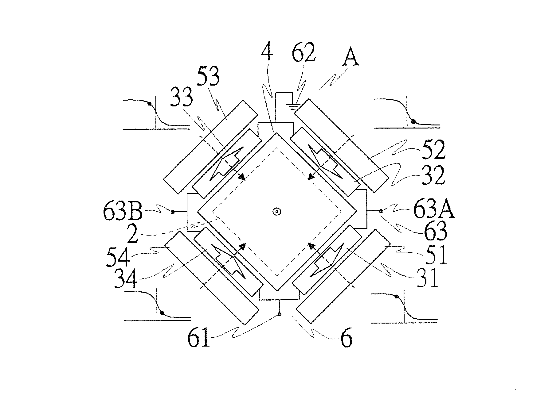
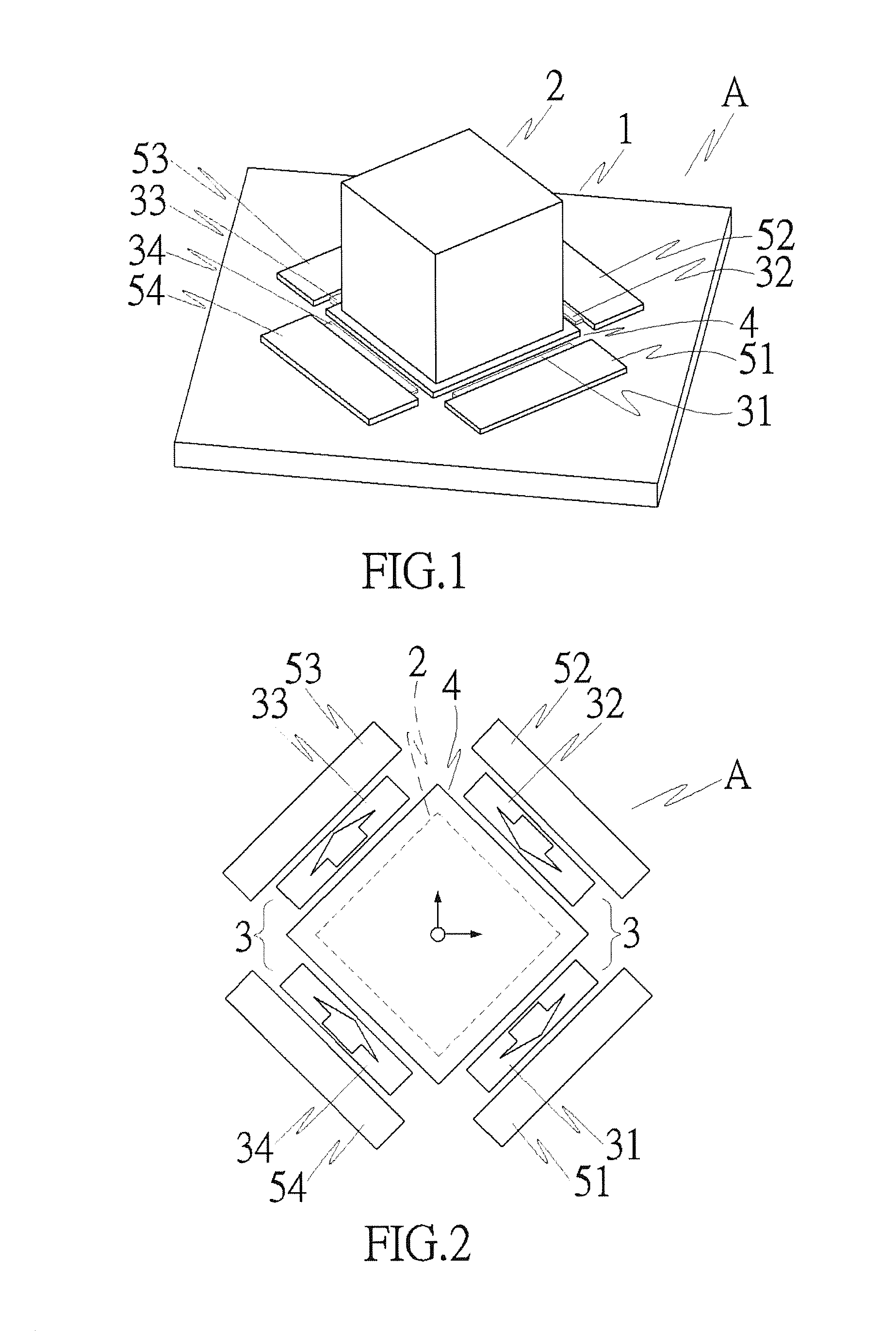
[0018]With reference to FIG. 1, a single bridge magnetic field sensor A according to the present invention includes a substrate 1. The substrate 1 can be of a type for producing magnetoresistive type sensing elements, but not limited to a silicon substrate.

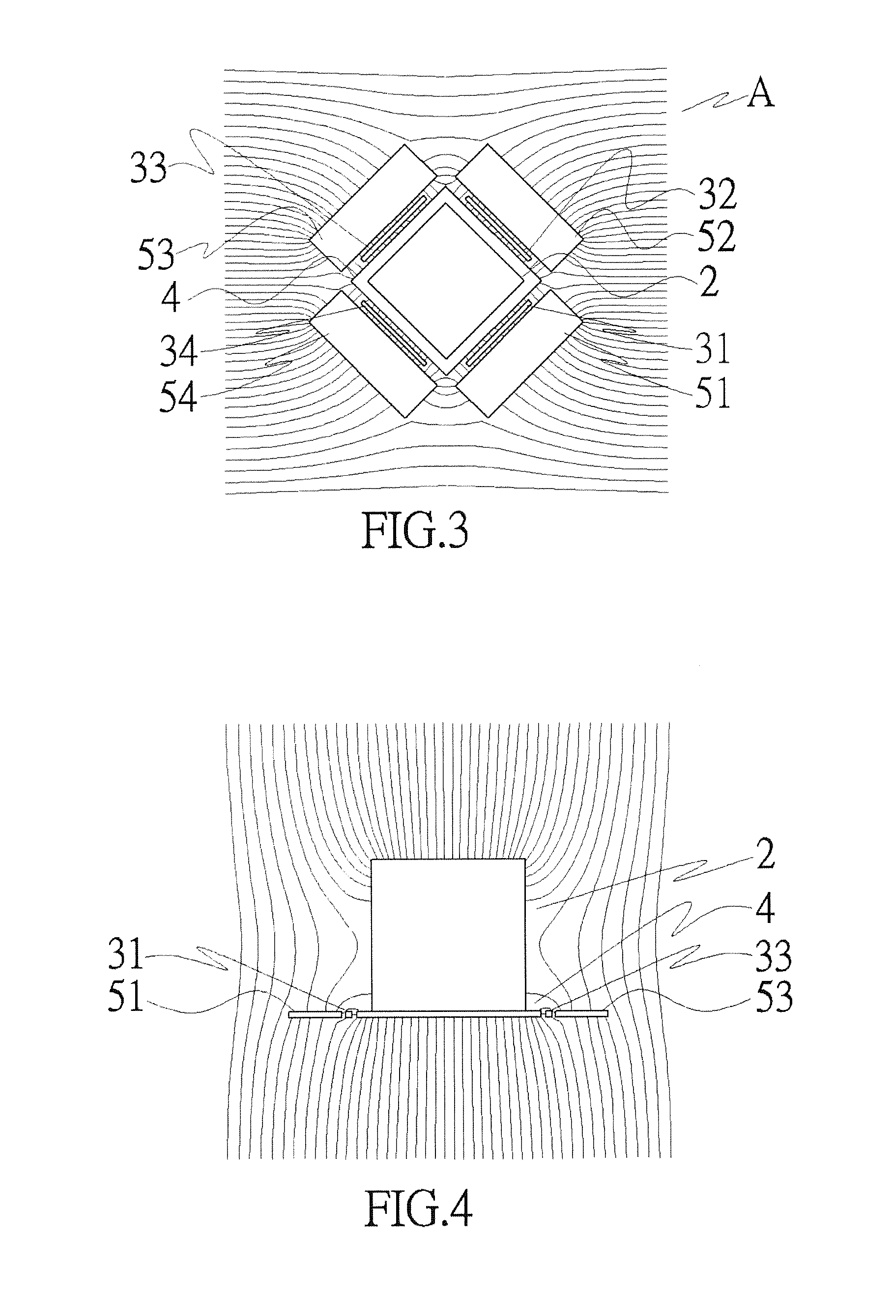
[0019]The single bridge magnetic field sensor A further includes a fluxguide 2. According to the form shown, the fluxguide 2 is a rectangular prism directly or indirectly mounted to a surface of the substrate 1. The fluxguide 2 is preferably made of a magnetically soft material having high magnetic permeability and low hysteresis, such as Ni—Zn ferrite or Ni—Fe alloy. With reference to FIGS. 3 and 4, the fluxguide 2 an refract a horizontal plane (including an X-axis direction and a Y-axis direction) of an externally applied magnetic field to a direction detectable by each magnetoresistive element 31, 32, 33, 34 mentioned hereinafter and can guide the externally applied magnetic field in a Z-axis direction to a horizontal direction...


PUM


Abstract

A single bridge magnetic field sensor includes a fluxguide mounted to a surface of a substrate. A bridge unit includes first, second, third, and fourth magnetoresistive elements mounted around the fluxguide and mounted on the surface of the substrate. A switching circuit is electrically connected to two voltage inputs, two grounding terminals, two voltage output terminals, and the four magnetoresistive elements. The switching circuit can proceed with circuit switching according to a magnetic field in each axis direction to be measured, thereby changing electrical connection between the voltage inputs, the grounding terminals, the voltage output terminals, and the four magnetoresistive elements. A measuring unit is electrically connected to the two voltage output terminals and the four magnetoresistive elements. The magnetoresistances of the four magnetoresistive elements measured by the measuring unit and output voltages of the voltage output terminals can be used to obtain a magnetic field measurement result.

Description

BACKGROUND OF THE INVENTION[0001]The present invention relates to an instrument for measuring magnetic fields and, more particularly, to a single bridge magnetic field sensor.[0002]A magnetic field sensor can detect magnetic field vectors in a space. However, indicating the direction of a magnetic field requires measurement on the same location to determine three magnetic field components orthogonal to one another. Although various vector magnetic field sensors are available, the measurement ranges of the magnetic field strength of these sensors are different. For example, Hall sensors are suitable for determining magnetic fields of 10 μT to 1 T, whereas reluctive sensors can detect magnetic fields of 1 mT to 0.1μ. Thus, different magnetic fields require different types of vector sensors. Furthermore, the three component sensors of currently available vector sensors are independent and are located in different locations, such that the whole device is large. Furthermore, the magnetic...

Claims


Application Information

Patent Timeline
IPC IPC(8): G01R33/09
CPCG01R33/0094G01R33/09G01D5/145G01R33/0011
Inventor CHANG, CHING-RAYJENG, JEN-TZONGHSU, JEN-HWALU, CHIH-CHENGLAI, BOR-LINLUONG, VAN-SU
Owner NAT TAIWAN UNIV
Why Eureka
Try Eureka