
Global Logical Timestamp

Active Publication Date: 2017-03-02
MICROSOFT TECH LICENSING LLC
View PDF9 Cites 6 Cited by
  • Summary
  • Abstract
  • Description
  • Claims
  • Application Information

AI Technical Summary

Benefits of technology

This patent describes a system that has multiple devices connected to a network. These devices have a global clock that ensures that each device can label an event with a specific timestamp. The invention combines the reliability of multiple local clocks to achieve a more accurate global timing. This can be useful in various applications where accurate and consistent timing is important.

Problems solved by technology

However, distributed systems do not have a global clock that accurately provides a time to every networked machine.
Further, distributed systems often experience independent failure of individual components within the system.

Method used


Image

  • Global Logical Timestamp
  • Global Logical Timestamp
  • Global Logical Timestamp

Examples


Embodiment Construction

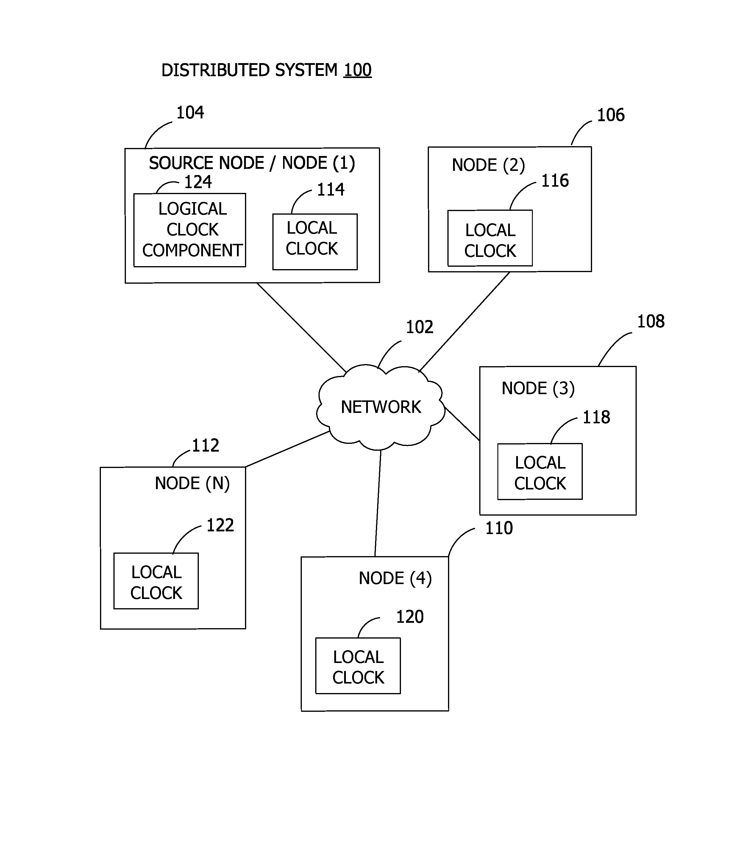
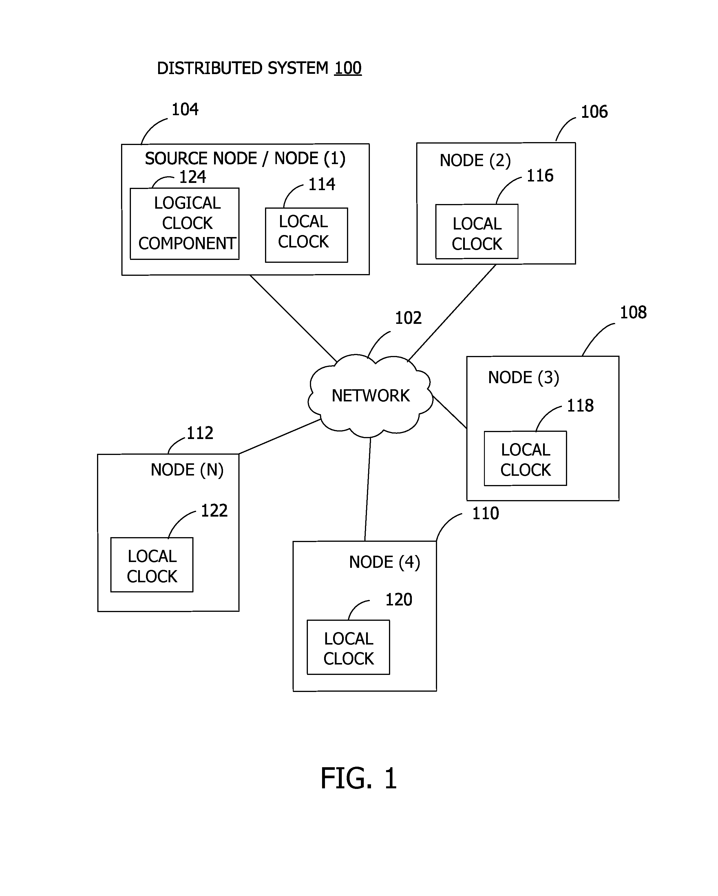
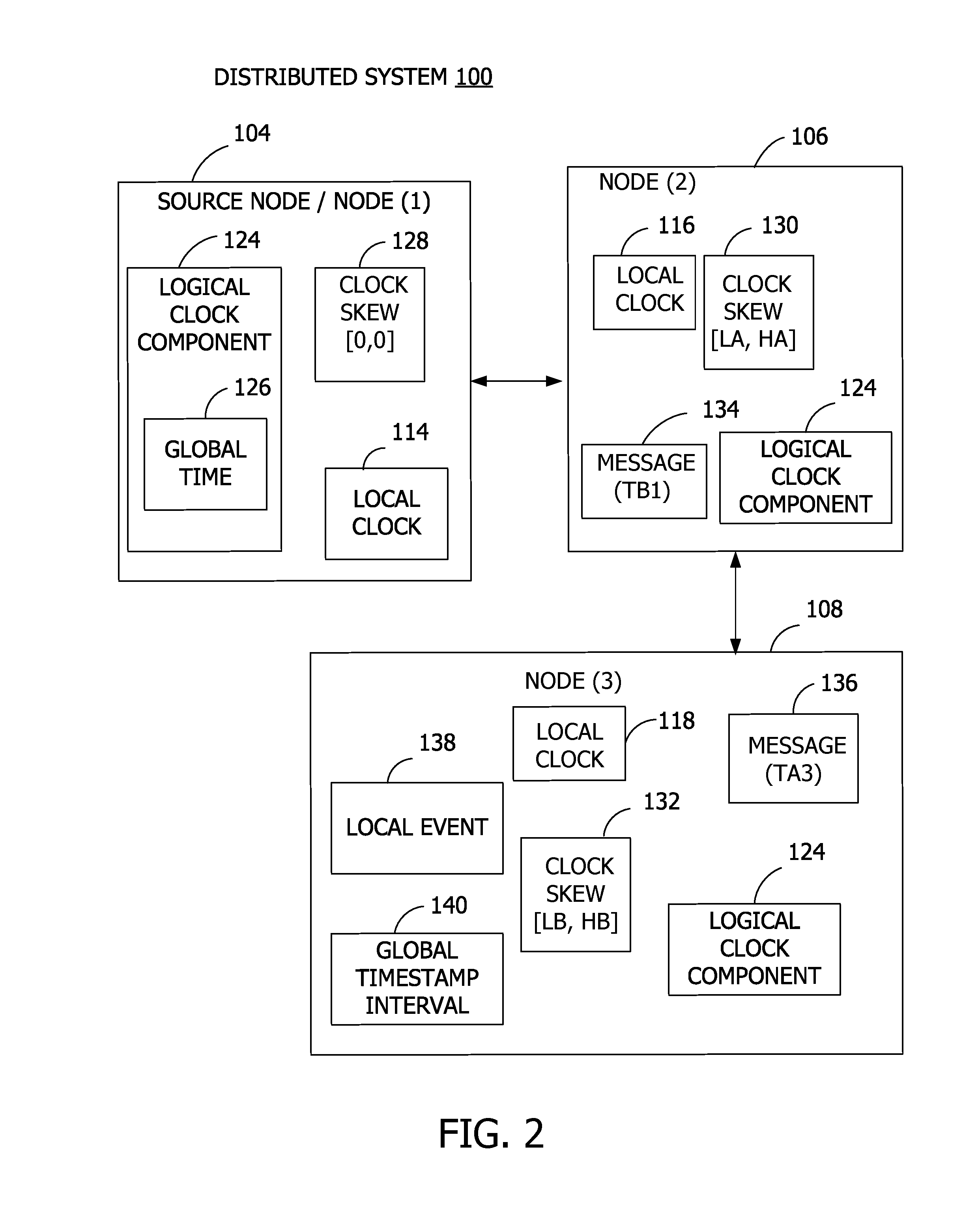
[0014]Referring to the figures, examples of the disclosure enable a global logical timestamp for a distributed computing system. In some examples, a global time source node provides a logical clock that sets a global time for the distributed system with bounded uncertainty, using message exchange between nodes of the system to propagate the global time with strong consistency.

[0015]Aspects of the disclosure further enable highly efficient system event ordering, conflict resolution, and staleness detection in a distributed computing system, with reduced error rates, based on the strong consistency and high availability of the logical clock. For example, in trace analysis, in order to identify whether event A is before or after some other event B, associated event timestamps may be used. In this example, if event A and event B occur on different machines within the distributed system, a determination has to be made as to which time to start searching for event A given the time for eve...


PUM


Abstract

Examples of the disclosure provide for providing a global timestamp in a distributed system. A plurality of nodes are connected via a network. A logical clock is implemented on a node of the plurality of nodes. The logical clock sets a global time for the network, such that another node of the plurality of nodes labels a local event with a global timestamp interval based on the global time provided by the logical clock.

Description

CROSS-REFERENCE TO RELATED APPLICATION[0001]This application claims the benefit of U.S. Provisional Application No. 62 / 209,244, filed Aug. 24, 2015, the entirety of which is hereby incorporated by reference herein.BACKGROUND[0002]Distributed systems are often characterized by components enabled to interact with each other in order to accomplish system tasks, such that one job or program is executed by more than one computer. In distributed systems, components of networked computers communicate and coordinate events by passing messages. However, distributed systems do not have a global clock that accurately provides a time to every networked machine. Further, distributed systems often experience independent failure of individual components within the system.SUMMARY[0003]Examples of the disclosure provide a system having a plurality of nodes connected to a network with a logical clock having bounded uncertainty between a plurality of local clocks such that any given node may label a l...

Claims


Application Information

Patent Timeline
IPC IPC(8): H04L29/08H04J3/06
CPCH04J3/0661H04L67/1095H04J3/0641H04J3/0667G06F1/14
Inventor XUN, LU
Owner MICROSOFT TECH LICENSING LLC
Learn More