
Reconfigurable control architectures and algorithms for electric vehicle wireless energy transfer systems

a wireless energy transfer and reconfigurable control technology, applied in the field of wireless energy transfer and methods, can solve the problems of affecting the reliability, safety performance, and low-level power delivery of the system, and affecting the reliability of the system, so as to achieve the effect of flexible design and implementation, without the risk of disrupting the control functions of the lower-level power electronics

Active Publication Date: 2017-03-09
WITRICITY CORP
View PDF18 Cites 5 Cited by
  • Summary
  • Abstract
  • Description
  • Claims
  • Application Information

AI Technical Summary

Benefits of technology

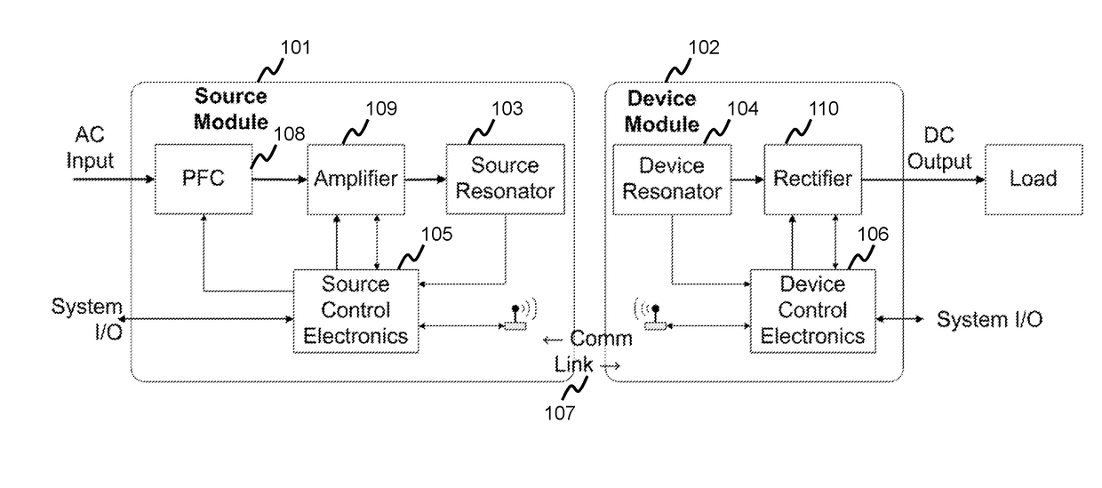
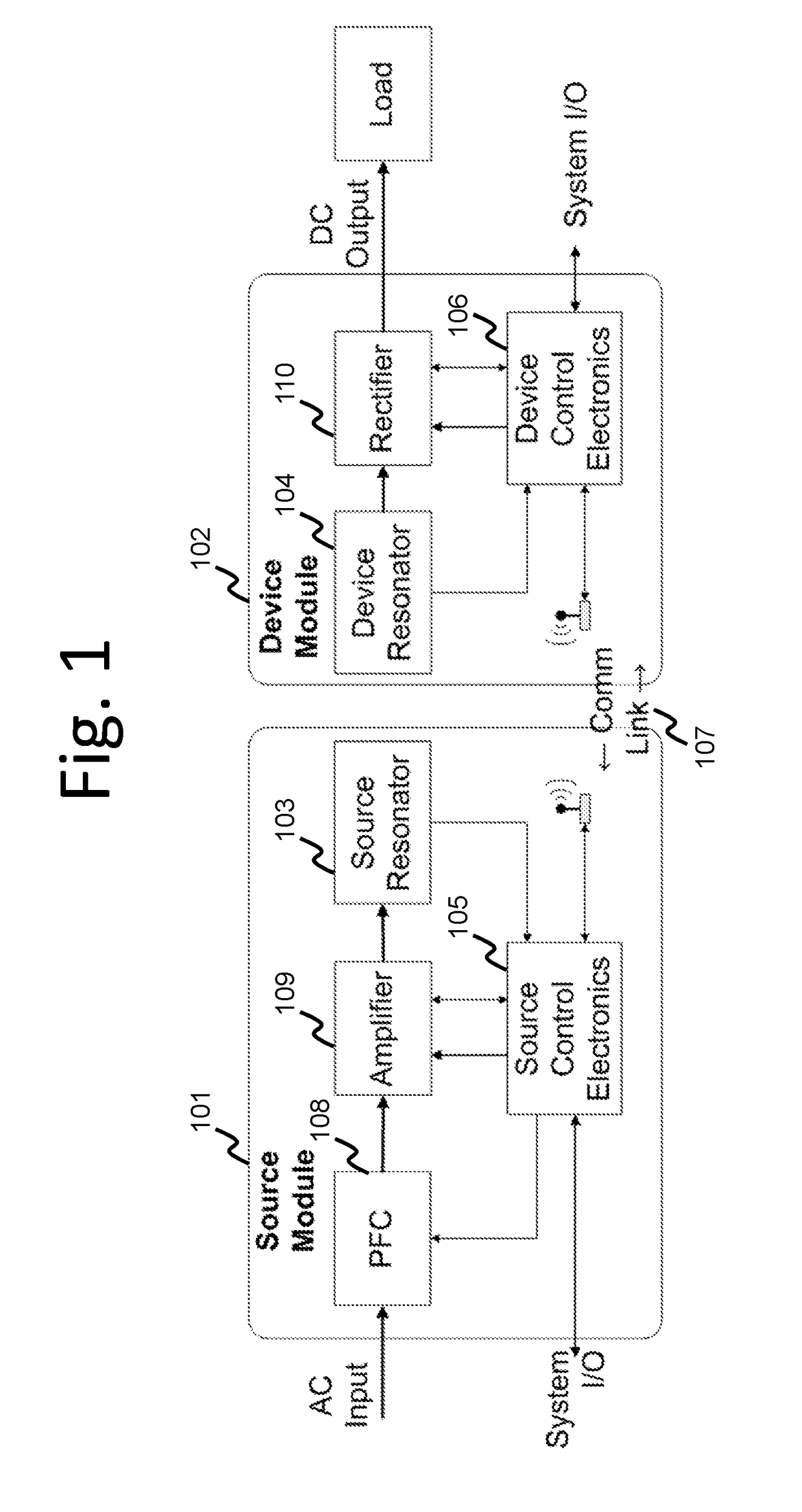
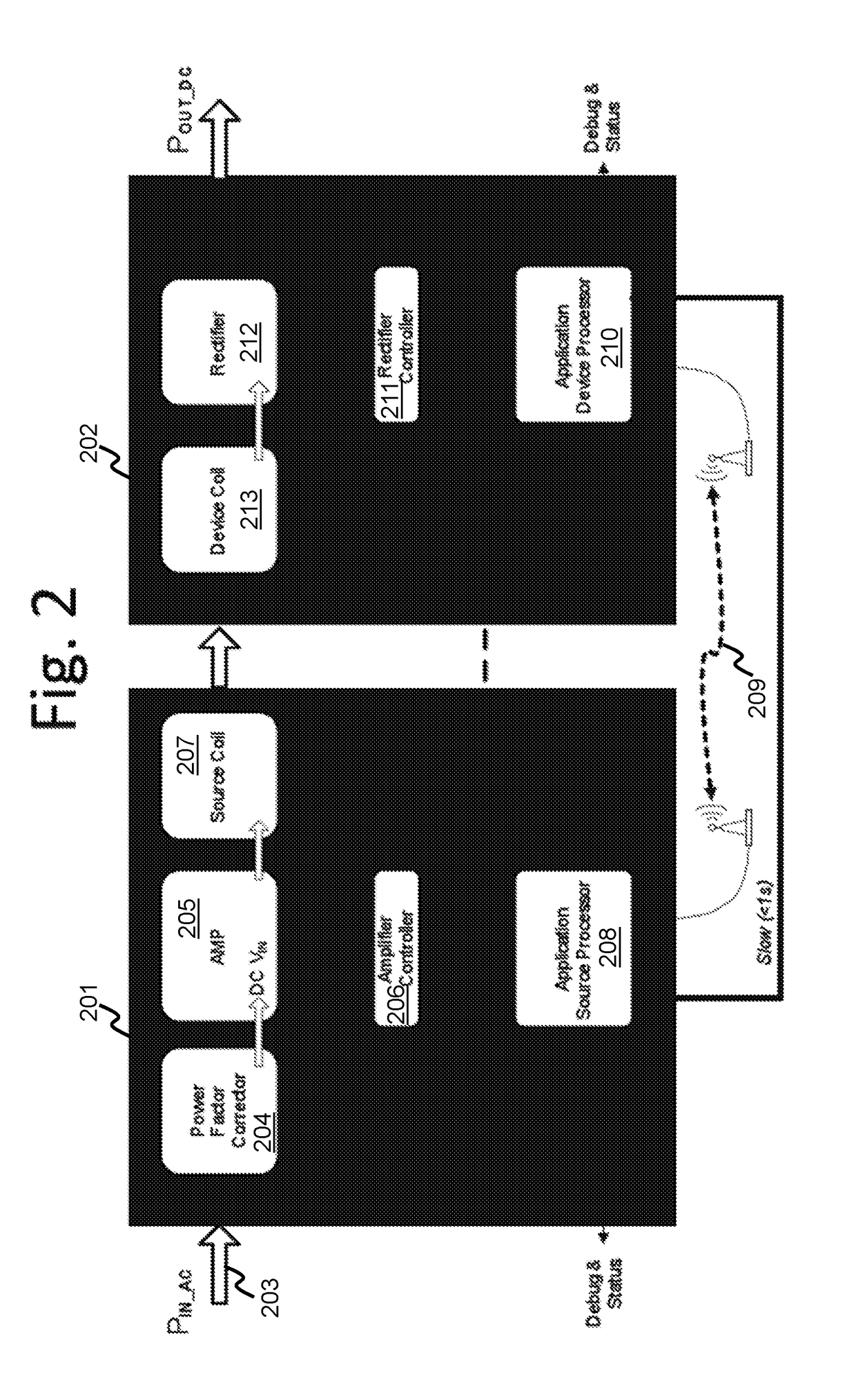
[0008]This invention relates to a control architecture for electric vehicle (EV) wireless power transmission systems that may be segmented so that certain essential and / or standardized control circuits, programs, algorithms, and the like, are permanent to the system and so that other non-essential and / or augmentable control circuits, programs, algorithms, and the like, may be reconfigurable and / or customizable by a user of the system. In addition, the control architecture may be distributed to various components of the wireless power system so that a combination of local or low-level controls operating at relatively high-speed can protect critical functionality of the system while higher-level and relatively lower speed control loops can be used to control other local and system-wide functionality. This combination of distributed and segmented control may offer flexibility in the design and implementation of higher level functions for end-use applications without the risk of disrupting lower level power electronics control functions.
[0009]The inventors envision that the control architecture may comprise both essential and non-essential control functions and may be distributed across at least one wireless source and at least one wireless device. Non-essential control functions may be arranged in a hierarchy so that, for example, more sophisticated users may have access to more, or different reconfigurable control functions than less sophisticated users. In addition, the control architecture may be scalable so that single sources can interoperate with multiple devices, single devices can interoperate with multiple sources, and so that both sources and devices may communicate with additional processors that may or may not be directly integrated into the wireless power charging system, and so on. The control architecture may enable the wireless power systems to interact with larger networks such as the internet, the power grid, and a variety of other wireless and wired power systems.

Problems solved by technology

The many disadvantages of using a charging cord, including the inconvenience, weight, and awkwardness of the cord, the necessity of remembering to plug-in and un-plug the vehicle, and the potential for cords to be stolen, disconnected, damaged, etc., have motivated makers of electric vehicles to consider wireless recharging scenarios.
The variety of available wireless power techniques and acceptable performance criteria may present challenges to system designers who may like to provide for interoperability between different wireless sources and wireless devices (usually integrated in the vehicles) and at the same time differentiate their products by offering certain enhanced features.
However, if the control architecture is not segmented to offer some reconfigurable functions while protecting the critical functions of the wireless power system, changing certain control loops and / or adding additional hardware may disrupt the required low-level power delivery, reliability, and safety performance of the system.

Method used


Image

  • Reconfigurable control architectures and algorithms for electric vehicle wireless energy transfer systems
  • Reconfigurable control architectures and algorithms for electric vehicle wireless energy transfer systems
  • Reconfigurable control architectures and algorithms for electric vehicle wireless energy transfer systems

Examples


Embodiment Construction

[0029]This disclosure describes exemplary reconfigurable system control concepts for electric vehicle wireless power transmission systems. In general, an electric vehicle (EV) may be any type of vehicle such as a car, a boat, a plane, a bus, a scooter, a bike, a cart, a moving platform, and the like that comprises a rechargeable battery. The wireless power transmission system may provide power to the battery charging circuit of the electric vehicle and / or it may power the vehicle directly. Wireless power may be provided to the vehicle while it is stationary or while it is moving. The power provided wirelessly to recharge the vehicle battery may be more than 10 Watts (W), more than 100 W, more than a kilowatt (kW), more than 10 kW, and / or more than 100 kW, depending on the storage capacity and power requirements of the vehicle. In some exemplary low power embodiments, fewer control loops and / or less distributed and / or less segmented control architectures may be sufficient to ensure s...


PUM


Abstract

A control architecture for electric vehicle wireless power transmission systems that may be segmented so that certain essential and / or standardized control circuits, programs, algorithms, and the like, are permanent to the system and so that other non-essential and / or augmentable control circuits, programs, algorithms, and the like, may be reconfigurable and / or customizable by a user of the system. The control architecture may be distributed to various components of the wireless power system so that a combination of local or low-level controls operating at relatively high-speed can protect critical functionality of the system while higher-level and relatively lower speed control loops can be used to control other local and system-wide functionality.

Description

CROSS-REFERENCE TO RELATED APPLICATIONS[0001]This application claims the benefit of U.S. provisional patent application 61 / 533,281 filed Sep. 12, 2011 and U.S. provisional patent application 61 / 566,450 filed Dec. 2, 2011.BACKGROUND[0002]Field[0003]This disclosure relates to wireless energy transfer and methods for controlling the operation and performance of electric vehicle wireless power transmission systems.[0004]Description of the Related Art[0005]Energy or power may be transferred wirelessly using a variety of known radiative, or far-field, and non-radiative, or near-field, techniques as detailed, for example, in commonly owned U.S. patent application Ser. No. 12 / 613,686 published on May 6, 2010 as US 2010 / 010909445 and entitled “Wireless Energy Transfer Systems,” U.S. patent application Ser. No. 12 / 860,375 published on Dec. 9, 2010 as 2010 / 0308939 and entitled “Integrated Resonator-Shield Structures,” U.S. patent application Ser. No. 13 / 222,915 published on Mar. 15, 2012 as 20...

Claims


Application Information

Patent Timeline
Patent Type & Authority Applications(United States)
IPC IPC(8): B60L11/18H02J50/12H02J50/80H02J7/02
CPCB60L11/182B60L11/1838H02J2007/0096H02J50/12H02J50/80H02J7/025B60L3/00Y02T90/14Y02T10/7072B60L53/60H02J7/00034B60L53/126B60L53/124H02J2310/48Y02T10/70Y02T90/12H02J50/60H02J50/90Y02T90/16
Inventor VERGHESE, SIMONKESLER, MORRIS P.HALL, KATHERINE L.LOU, HERBERT TOBYFIORELLO, RON
Owner WITRICITY CORP
Learn More