Unlock instant, AI-driven research and patent intelligence for your innovation.

Columnar laminar flow generation device and method for generating columnar laminar flows

a technology of laminar flow and generation device, which is applied in the direction of electrical equipment, chemistry equipment and processes, cleaning processes and utensils, etc., can solve the problems of substantial achieve the reduction of the reduction of the energy required to control the temperature and humidity of the replacement gas, and the reduction of the use of energy. , the effect of reducing the required quantity of filters

Active Publication Date: 2017-03-16
NAT INST OF ADVANCED IND SCI & TECH +2
View PDF1 Cites 0 Cited by
  • Summary
  • Abstract
  • Description
  • Claims
  • Application Information

AI Technical Summary

Benefits of technology

The present invention proposes a columnar laminar flow generation device that can adjust the velocity of laminar flows according to the gas suction rate. This allows for the generation of laminar flows at any flow velocity, not limited to a certain speed. By reducing the required amount of replacement gas, the device can be made smaller and energy usage can be reduced. The device can be used in a variety of applications such as wafer processing and rotary application, achieving the same degree of cleanliness without the need for excessive amounts of replacement gas. Additionally, the device allows for size reduction of the fan needed to push out the replacement gas and purifies the gas using a filter. Overall, the present invention provides a more efficient and cost-effective solution for generating laminar flows in various industrial settings.

Problems solved by technology

Also, providing a filter in the feed pipe is all that is needed to purify the replacement gas, which substantially decreases the required quantity of filters.

Method used


Image

  • Columnar laminar flow generation device and method for generating columnar laminar flows
  • Columnar laminar flow generation device and method for generating columnar laminar flows
  • Columnar laminar flow generation device and method for generating columnar laminar flows

Examples


example 1

[0104]The columnar laminar flow generation device proposed by the present invention was installed in the spin cup of a minimal resist coating device.

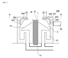
[0105]The columnar laminar flow generation device 100 used in Example 1 conforms to the perpendicular section view shown in FIG. 2 above and the horizontal section view shown in FIG. 4 above. The replacement gas travels through the flow passage 24 having four connection paths 242 and 16 slits 245 and is distributed accordingly, and then blows out upward from the gas blow-out port 22.

[0106]The diameter of the opening 21 is 34 mm, and the width of the gas blow-out port 22 provided in the interior wall of the opening 21 is 2 mm.

[0107]The replacement gas is dry air of 24° C. in temperature that has passed through a HEPA filter, while the blow-out rate is 6 L / min, suction rate is 3 L / min, and velocity of columnar laminar flows calculated from the area of the opening and the suction rate is 55 mm / sec. Clean downflows are supplied to the proce...


PUM


Abstract

A columnar laminar flow generation device includes: a placement part on which to place a processing target; a gas blow-out part having an opening; and a gas suction path; wherein the placement part is positioned in a space whose outer periphery surface is constituted by extending the interior wall of the opening in the direction vertical to the opening; the opening has, in its interior wall, a gas blow-out port through which a gas is blown out in one direction vertical to the opening; and the gas suction path is formed in such a way that it suctions the gas in the direction opposite to the one in which the gas is blown out. The columnar laminar generation device is capable of generating columnar laminar flows.

Description

BACKGROUND[0001]Field of the Invention[0002]The present invention relates to a columnar laminar flow generation device, as well as a method for generating columnar laminar flows.[0003]Description of the Related Art[0004]In such technical fields as semiconductor manufacturing, MEMS manufacturing, image display device manufacturing, ultraviolet light irradiation treatment and coating, there is a practice of controlling the ambience constant by discharging gases while introducing a replacement gas whose cleanliness level, gas type, etc., have been controlled, in order to eliminate dust and other foreign matters, eliminate active gases, and control temperature and humidity, etc.[0005]Discharging gases containing foreign matter, etc., active gases, and gases whose temperature and humidity are not desired (hereinafter referred to as “gases to be replaced”) is difficult if a replacement gas is arbitrarily blown into the space because it only disturbs the flows of gases and generates turbul...

Claims


Application Information

Patent Timeline
IPC IPC(8): B08B5/02H01L21/02
CPCH01L21/02057B08B5/02B08B15/00H01L21/67017H01L21/6715
Inventor OKUDA, SHUUJIKHUMPUANG, SOMMAWANHARA, SHIROTAKEUCHI, SHOSENSU, YOSHIHISAITO, TAKAHIRO
Owner NAT INST OF ADVANCED IND SCI & TECH