Handheld work apparatus

a work tool and hand-held technology, applied in the direction of working accessories, metal sawing accessories, gearing, etc., can solve the problem of high brake force of the work tool, and achieve the effect of low cut-off wheel inertia and great brake for

Active Publication Date: 2017-03-16
ANDREAS STIHL AG & CO KG
View PDF21 Cites 12 Cited by
  • Summary
  • Abstract
  • Description
  • Claims
  • Application Information

AI Technical Summary

Benefits of technology

[0007]It is an object of the invention to provide a work apparatus which makes braking of the work tool possible independently of the rotational speed of the work tool.
[0008]It is provided that the brake unit acts on the belt drive of the work apparatus. Here, the brake unit can act on the belt drive directly or indirectly, for example via a clutch drum. The belt drive is coupled to the work tool independently of the rotational speed of the work tool, with the result that braking of the work tool is possible via the belt drive at every rotational speed. In particular at high rotational speeds and if the work tool is a work tool with a great moment of inertia, for example a cut-off wheel, high forces are required to brake the work tool. In order to reduce the required forces, it is provided that the work apparatus has at least one first drive belt of a first drive stage and a second drive belt of a second drive stage. The first and the second drive stage in each case bring about a reduction in the rotational speed. Accordingly, the rotational speed of the driven pulley of each drive belt is lower than the rotational speed of the driving pulley of the drive belt. A sufficiently large rotational speed reduction with an overall compact configuration can be achieved by way of the at least two-stage configuration of the belt drive. The reduction in the rotational speed of the work tool brings about a reduction in the inertia forces on the work tool, with the result that braking of the work tool via the belt drive is made possible. In order to achieve a reliable transmission of the braking force to the work tool, it is provided that at least one redirection roll bears against at least one drive belt. The tension in the drive belt is maintained via the redirection roll and lifting up of the drive belt from the pulley is avoided. As a result, the transmission of a sufficiently great braking moment to the work tool can be ensured. Here, the redirection roll advantageously enlarges the wraparound angle on at least one pulley, over which the at least one drive belt is guided. As a result, a rapid standstill of the work tool can be achieved by way of the brake unit.
[0009]At least one redirection roll bears against the drive belt, via which the highest drive moment is transmitted during operation. This is, in particular, the second drive belt which drives the second pulley which is connected fixedly to the work tool so as to rotate with it. As a result of the reduction in the rotational speed in every drive stage, the torque to be transmitted via the respective drive belt increases accordingly. In particular in the case of drive belts which transmit a high drive moment, lifting up of the drive belt from the pulley can be avoided in a simple way via the redirection roll.

Problems solved by technology

In particular at high rotational speeds and if the work tool is a work tool with a great moment of inertia, for example a cut-off wheel, high forces are required to brake the work tool.

Method used


Image

  • Handheld work apparatus
  • Handheld work apparatus
  • Handheld work apparatus

Examples


Embodiment Construction

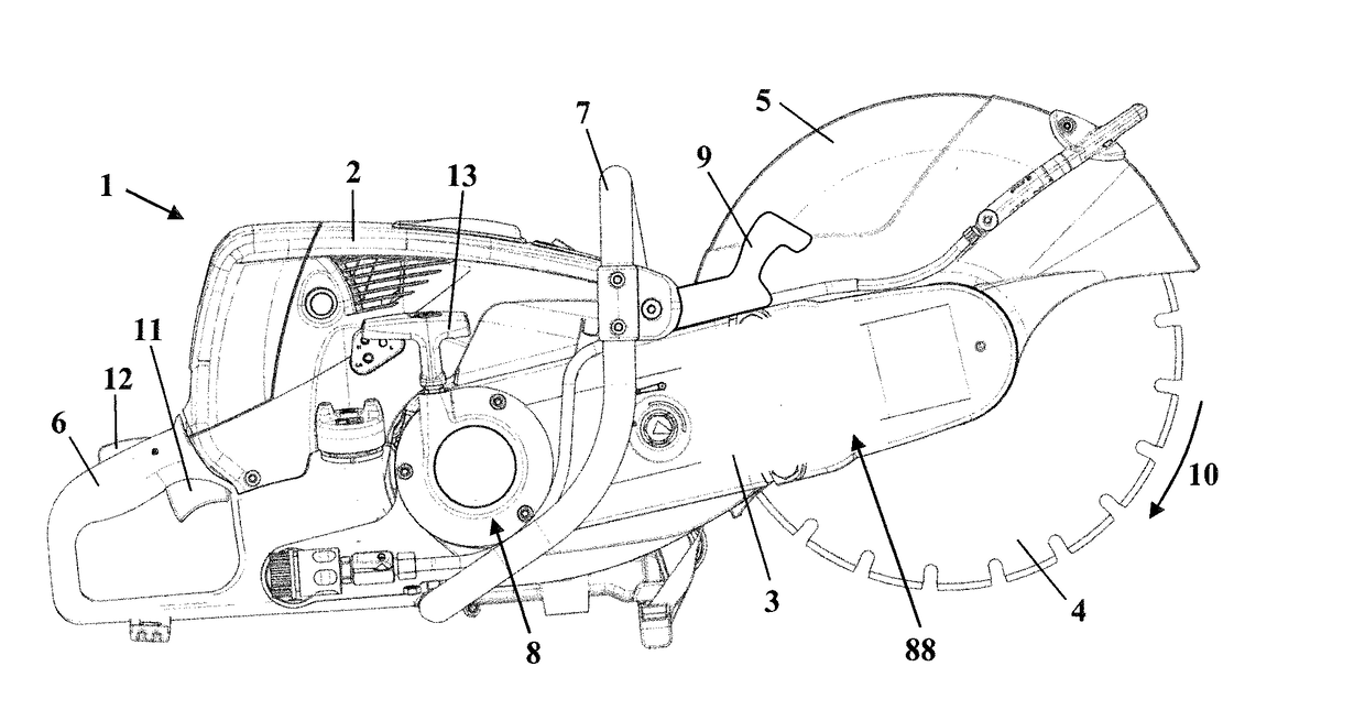
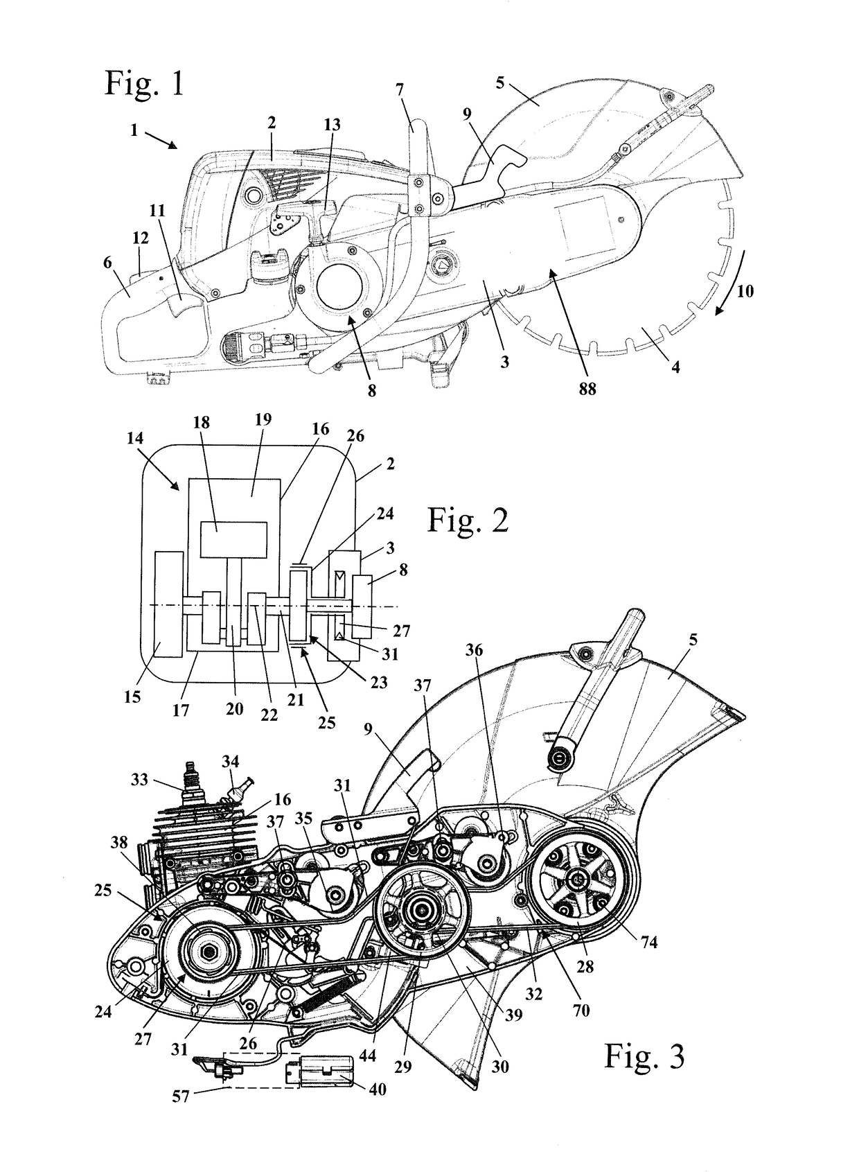
[0039]FIG. 1 shows a cut-off machine 1 as an example of an embodiment for a handheld work apparatus. The cut-off machine 1 has a housing 2, on which a cantilever 3 is fixed. A work tool 4, namely a cut-off wheel, is mounted rotatably at the free end of the cantilever 3. During operation, the work tool 4 is driven so as to rotate in a rotational direction 10. The work tool 4 is covered over part of its circumference by a protective cover 5 which, in the embodiment, is configured in one piece with a housing part 39 (FIG. 3) of the cantilever 3. The protective cover 5 and the housing part 39 of the cantilever 3 can, for example, be made of metal and can be manufactured in a casting process. The cantilever 3 includes a cover 88 which closes the housing part 39. An actuating element 9 is arranged on the cantilever 3. The actuating element 9 is configured as an actuating lever in the embodiment and serves to actuate a brake unit which will be described in greater detail in the following t...


PUM

PropertyMeasurementUnit
wrap angleaaaaaaaaaa
wraparound angleaaaaaaaaaa

Abstract

A handheld work apparatus has a drive motor which drives a work tool rotationally via a belt drive. The belt drive has a first, driving pulley and a second, driven pulley. The second pulley is connected fixedly to the work tool so as to rotate therewith. The rotational speed of the second pulley is lower during operation than that of the first pulley. A brake unit acts on the belt drive. A first drive belt of a first stage and a second drive belt of a second stage act between the pulleys to transfer the drive torque. The belts each bring about a rotational speed reduction. The belt drive includes a redirection roll which bears against the belt, via which the highest drive torque is transmitted during operation. As a result, a braking operation of the work tool is enabled independently of the rotational speed of the tool.

Description

CROSS REFERENCE TO RELATED APPLICATIONS[0001]This application is a continuation application of international patent application PCT / EP2015 / 001007, filed May 15, 2015, designating the United States and claiming priority from German application 10 2014 007 878.7, filed May 24, 2014, and the entire content of both applications is incorporated herein by reference.BACKGROUND OF THE INVENTION[0002]U.S. Pat. No. 6,039,037 has disclosed a cutting machine which is driven by internal combustion engine and the work tool of which is driven via a belt drive. Here, the diameter of the driving pulley is smaller for the two belts of the belt drive than the diameter of the driven pulley, with the result that the rotational speed of the work tool is lower than the rotational speed of the internal combustion engine.[0003]A work apparatus is disclosed in U.S. Pat. No. 8,469,167. The work apparatus includes a brake unit which acts on the clutch drum. The brake unit is held in the release position during...

Claims


Application Information

Patent Timeline
Patent Type & Authority Applications(United States)
IPC IPC(8): B23D47/12B23D45/16B27B5/38
CPCB23D47/12B23D45/16B27B5/38B23D47/00B23D59/00B23Q11/00B24B55/10B26D7/18B28D1/04B28D7/02F16D43/14B27B9/00F16H7/02F16H7/1281F16H55/36F16H2007/0806F16H2007/0865F16H2007/0893
Inventor HANUSSEK, SEBASTIANRIEGER, JAN
Owner ANDREAS STIHL AG & CO KG
Why Eureka
Try Eureka